


e-STUDIO160/200/250 ADJUSTMENT ITEMS 1 - 26 December 2002 TOSHIBA TEC
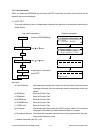
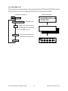
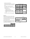
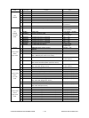
• Explanation of status display
When the sensor test is carried out, the status
of each sensor is indicated on the display with
0 or 1.
Each signal is divided into 8-bit blocks.
The character on the left edge of the display
indicates as follows:
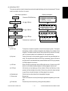
A: Signal input to ASIC
I: Signal input to the IO port
S: Signal from the scanner or R/ADF
P: Signal from the option connected to the
PFC
The display is switched using the or key.
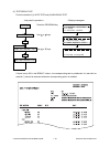
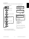
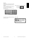
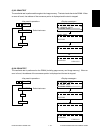
Example 1:
Confirm whether the front cover is open or close.
The front cover is equipped with the 24-V ON/OFF
switch (Interlock switch) and the front cover switch.
The status of both switches is 1 when the cover is
open, and 0 when it is close.
When the status of the one is 0 and that of the other
is 1 as shown in the example, there is something
wrong with either of these switches.
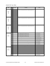
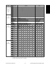
A
I
A1
IO1
IO4
IO7
A2
IO2
IO5
IO8
A3
IO3
IO6
S
P
S1
S3
P1
P4
S2
S4
P2
P5
P3
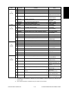
Status display example
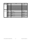
A
I
IO3 Bit1
01001010 00100010 00000001
01001010 00100010 00000001
01001110 00100000 00000001
00001010 00100110
IO4 Bit2
Open Close
IO3 bit 1 (Interlock switch) 1 0
IO4 bit 2 (Front cover switch) 1 0
Front cover