


11
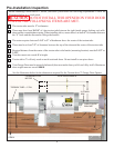
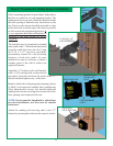
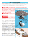
Step 8: Photoelectric Safety Sensor Installation
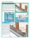
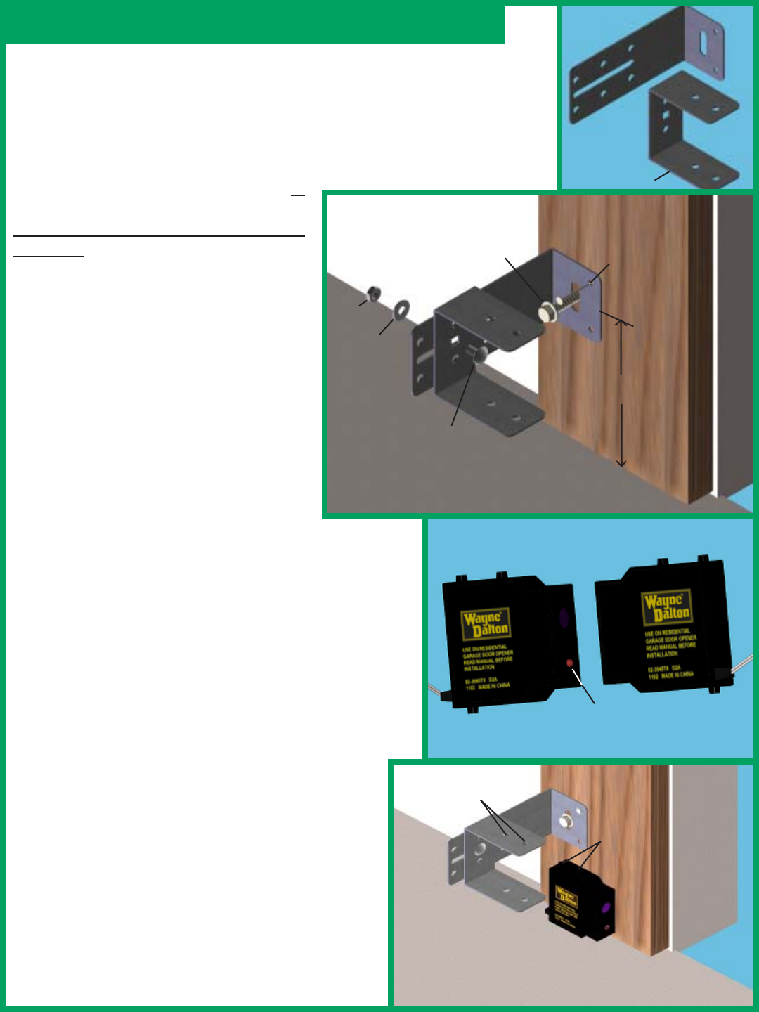
Select a mounting position no more than 5 inches above
the floor to center line of wall mounting bracket. The
sending and receiving units should be mounted inside
the door opening to minimize any interference by the
sun. However, the sensors should be mounted as close
to the door track or inside edge of the door as possible
to offer maximum entrapment protection. It
is very important that both wall brackets be
mounted at the same height for proper
alignment.
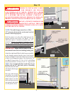
The brackets may be temporarily mounted
to the jamb with a 1" flat head nail (provided)
using the small hole above the slot. Using
two 5/16 x 1-1/2" lag screw (provided),
permanently mount the wall mounting
brackets to both door jambs. In some
installation it may be necessary to attach a
wooden spacer to the wall to achieve the
required clearance.
Attach the “U” brackets to the wall brackets
with a 1/4-20 carriage bolt, washer and nut
(provided). Insert the bolt from the inside of the “U”
bracket and hand tighten only, at this time.
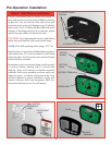
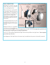
Identify which side of the garage door opening (if any)
is “likely” to be exposed to sunlight. Since sunlight may
affect photoelectric sensors, you should mount the
sending unit (not the receiving unit) on the side of the
door opening most exposed to the sun.
NOTE: If wires must be lengthened or spliced into
prewired installation, use wire nuts or suitable
connectors.
Attach the sending and receiving units to the “U”
brackets by inserting their tabs into the respective holes.
WALL
MOUNTING
BRACKET
NUT
WASHER
1/4-20 X 1/2”
CARRIAGE BOLT
(1) 5/16 X 1-1/2”
LAG SCREWS
5”
“U” BRACKET
RECEIVING UNIT
SENDING UNIT
HAS NO LED
LIGHT
LED ALIGNMENT
LIGHT
TABS
TOP & BOTTOM
TAB HOLES
TOP & BOTTOM
NAIL
DOOR
JAMB