


23
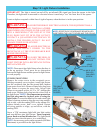
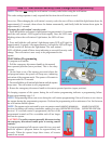
Step 19: Custom Settings
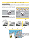
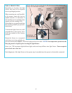
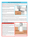
Step 20: Photoeletric Safety Sensor Alignment
Custom pet position: Normal install routine sets the
pet open position to approximately eight inches above
the ground. The pet opening height may be changed to
open anywhere between 8" and 30" above the ground.
To change the automatic pet opening height use the
following procedure:
1. After completion of the normal install routine, with
the door in the closed position, place the disconnect
handle in the manual operated position.
Manually position the door to the desired pet opening
height (between 8" and 30" above ground) and return disconnect handle to the motor operated position.
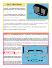
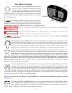
2. Simultaneously depress the pet and up/down buttons on the wall station. The opener will beep once. The pet
button is now programmed to automatically open the door to this custom height.
NOTE: The opener will NOT accept programmed pet lock position if door is below 8" or higher than 30".
NOTE: Activation of the normal install routine will reset the pet position to the default eight inch target
height. For use of the pet button see Operation section.
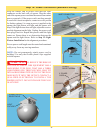
IMPORTANT! - This infrared safety sensor sends an invisible beam of light from the sending unit to the receiving
unit across the pathway of the door. The door opener will not operate until the safety sensor is connected to the
power unit and properly aligned. If the invisible beam of light is obstructed, an open door cannot be closed by the
transmitter or a momentary activation of the wall mounted push button. However, the door may be closed by
holding your finger on the wall push button (constant pressure) until the door travels to a fully closed position.
At this point you will be able to activate the opener; it will open, but will not close the door unless the sensors are
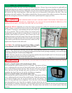
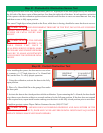
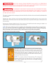
aligned. The safety sensors can be aligned by moving the sending and receiving units in or out (see Fig. 1)until the
alignment light on the receiving unit comes on. The 1/4-20 carriage bolt can be loosened to move the unit in or
out, as required. If you have difficulty aligning
beams, check that both brackets are mounted
at the same height and remount if necessary.
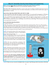
Additional minor adjustments can be made by
lightly bending the mounting brackets (see
Fig. 2).
WARNING FAILURE TO
MAKE ADJUSTMENTS COULD RESULT
IN SEVERE OR FATAL INJURY.
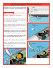
Once the alignment light comes on, tighten all
bolts and mounting screws. Finish securing all
wire making sure not to break or open any of
the conductors. Loop and secure any extra
wire. Now, using the wall station’s up/down
button, activate the opener and check that it
will operate through full open and close cycles.
UP/DOWN
BUTTON
PET BUTTON
1/4-20 CARRIAGE BOLTS
Top View
Align in Center
(In/Out)
Top View
Align in Center
For this adjustment bend bracket at
wall mount
FIG. 1
FIG. 2
IN
OUT
IN
OUT