


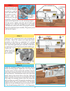
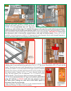
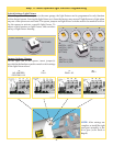

Lubricate both right
hand and left hand gear
assemblies, with the
grease provided. Place
the opener over the 1"
torsion tube and
between the two gear
assemblies. Center the
opener mounting bracket over the mounting support.
Lift the opener slightly and slide the left hand gear
assembly over so that the left hand drive gear meshes
with and rests on the teeth of the left hand gear assembly.
Repeat for right hand gear assembly. Plug motor power
cord into the opener.
Tighten the 3/8" square head bolt on the left hand gear
assembly. Adjust the opener and right hand gear
assembly so that there is a minimum 1/8" spacing
between the opener and the left hand gear assembly.
Now, adjust the right hand gear assembly, so that there
is a minimum 1/8" spacing between opener and the gear.
Tighten the 3/8"
square head bolt
on the right hand
gear assembly.
8
Step 3
Step 4
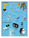
GREASE
PACKET
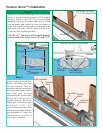
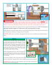
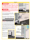
Adjust the mounting bracket so that it fits flush with the
header/ mounting support. Tighten the 5/16-18 nuts. Next,
level the opener with the torsion tube and door. Near the
cable drum, measure the distance from the torsion tube to
the top of the door. This dimension must be the same at the
opener point on the torsion tube to the door. Adjust the
opener vertically (if necessary) to accommodate this. Mark
a line under the mounting bracket when the torsion tube
and top of door are parallel. Keeping the mounting bracket
aligned with the line, secure the bracket to the mounting
support by first pre-drilling the lag screw locations with 3/
16” dia. bit and fastening with (2) 5/16” x 1-5/8” lag screws.
Step 5
GEAR ASSEMBLIES
1” TORSION
TUBE
1” TORSION
TUBE
OPENER
RIGHT HAND
DRIVE GEAR
1/8”
1/8”
OPENER
LEFT HAND
GEAR
ASSEMBLY
RIGHT HAND
GEAR
ASSEMBLY
3/8” SQUARE HEAD BOLT
PLUG IN MOTOR
POWER CORD
GREASE
ALL TEETH
IN GEAR
(2) 5/16” X 1-5/8”
LAG SCREWS
MOUNTING
BRACKET
SUPPORT
FOUNDATION
5/16-18 NUTS