


18
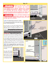
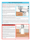
Step 13: Power Connection (Permanent Wiring Option)
Where required by local codes, the opener must be
permanently wired. Services of a licensed electrician can
be obtained to perform the following permanent wiring
procedure.
WARNING TO AVOID ELECTRICAL
SHOCK, DISCONNECT POWER AT FUSE/
BREAKER BOX BEFORE PROCEEDING.
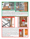
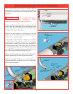
Using a phillips head screwdriver, remove the two
screws from the right hand cover and unplug motor
power cable. Remove right hand cover from the opener
to expose electronics and wiring.
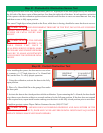
Remove the inlet connector, including its wires and
discard. Install the hardwire plate provided, using (2)
#6-25 x 1/4" screws provided.
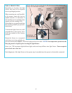
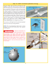
Attach conduit, insert field wires and cut wires to allow
an additional 6" of length. Strip off 3/4" of insulation
from each wire. Install wires to the screw terminals on
the circuit board with a 360 degree loop, as shown in
lower left illustration. Black wire to BLK terminal, white
wire to WHITE terminal and the green with yellow stripe
wire to the frame with the provided #8 screw.
Position wiring as shown in the lower left illustration,
keeping them to the left side of the circuit board.
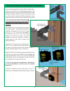
Replace the right hand cover over the opener’s
electronics and secure with the two screws. Plug motor
power cable into opener.
HARD WIRE
PLATE
(2) SCREWS
#6-25 X 1/4”
CONDUIT
NUT
CONDUIT
INLET
CONNECTOR
CONDUIT
CONDUIT
NUT
GREEN/YELLOW
(GROUND)
WHITE
(NEUTRAL)
BLACK
(LIVE)
(2) SCREWS
MOTOR
POWER
CABLE
360 LOOP
#8 SCREW