


21
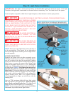
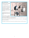
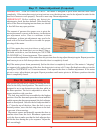
During install routine, the door will move up and down twice. Always keep a moving door in sight and keep
people and objects away until it is completely closed. Pull the emergency disconnect handle to the manual door
operated position (lower position). Manually raise the door to the full upward position. Then manually lower
the door to the fully closed position. Make sure there are no obstructions in the path of the door. Also, pay
attention to the cable snubbers. The snubbers should allow free movement of the cables in and out of the drums.
Return the emergency disconnect handle to the motor operated position (upper position).
WARNING THE OPENER SHOULD ONLY BE DISCONNECTED WHILE THE DOOR IS IN
THE CLOSED (DOWN) POSITION. OTHERWISE, IN CASE OF WEAK OR BROKEN SPRING(S), THE
DOOR COULD FALL, CAUSING SEVERE OR FATAL INJURY.
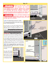
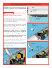
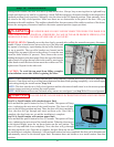
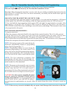
HELPFUL HINTS: Manually move the door slowly upwards after pulling the manual emergency disconnect
handle. If there is interference between the top of the door and
the opener’s housing try repositioning the top roller bracket as
far up as possible. The top roller brackets are located on the
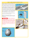
Garage Door top panel (closest to the ceiling). Loosen the nuts
from the slider bracket (if present). Then, remove the screws
holding the bracket to the door panel. Raise the top roller bracket
and re-attach. Re-align the top roller in the track by moving the
slider bracket until the door section meets the weather seal. Re-
tighten nuts. Repeat for the other side.
CAUTION: To avoid the top panel from falling, complete
re-installation on one side before beginning the other.
NOTE: If no obstructions interfere with the door when manually opened and closed, proceed to Step 16 a.
However, if an object such as a ceiling beam obstructed the door from opening completely, set a custom upper
limit setting during the install routine, Step 16 b.
NOTE: The door must be in its fully closed position and the disconnect handle must be in the motor operated
position (upper position) to initiate the install routine.
NOTE: Install routine will not run if infrared safety sensors are not aligned. (see Step 20 for IR sensor alignment.)
WARNING TO AVOID INJURY, NO ONE SHOULD CROSS THE PATH OF A MOVING DOOR!
HELPFUL HINTS:
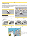
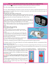
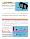
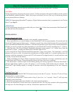
Step 16 a: Install routine with standard upper limit
Press and hold the profile button for five (5) seconds. The opener will beep
twice, indicating the activation of the install routine. The door will now
move to the full open position and stop. Then, the door will close completely.
Next, the door will go through one more up/down cycle. Once this is
complete, the door limits are set and the installation is complete.
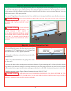
Step 16 b: Install routine with custom upper limit
Press and hold the profile button for five (5) seconds. The opener will beep
twice, indicating the activation of the install routine. When the door moves
to the desired height, press the up/ down button on the wall station. The
door will stop and then close completely. Next, the door will go through
one more up/down cycle. Once this is complete, the door limits are set and
the installation is complete.Alternately: After an install routine has been completed, the door can be disconnected
and manually moved to the desired upper limit. Reconnect door and initiate a new install routine from that
position.
Step 16: Install Routine
SLIDER
BRACKET
TOP
BRACKET
SCREWS
TOP
ROLLER
HORIZONTAL
TRACK
BOLTS AND NUTS
UP/DOWN
BUTTON
PROFILE
BUTTON