


14
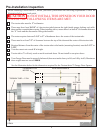
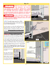
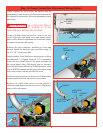
Step 10
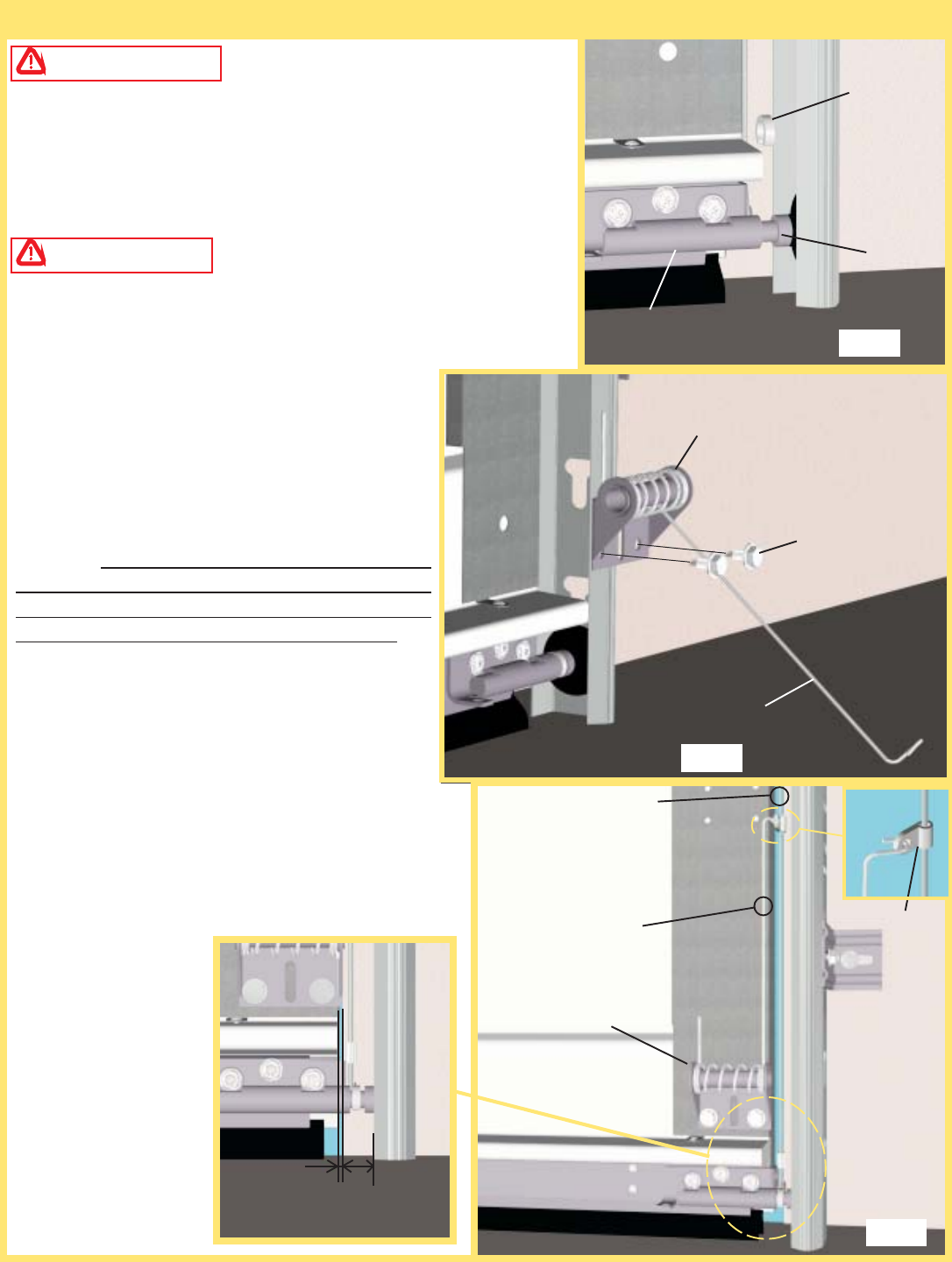
SPACER
ROLLER
CABLE KEEPER
ASSEMBLY
1/8”
1/2”
(2) 1/4 X 11/16”
SELF DRILLING
SCREWS
COUNTERBALANCE
CABLE
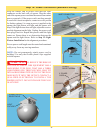
CABLE KEEPER
ASSEMBLY
(INSTALLED)
BOTTOM
BRACKET
CABLE
KEEPER ARM
PLASTIC
SLEEVE
CABLE
KEEPER ARM
FIG.1
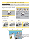
FIG.2
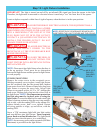
FIG.3
WARNING PRIOR TO INSTALLING CABLE
KEEPERS, CHECK FOR BROKEN OR FRAYED
COUNTERBALANCE CABLES. OPERATING A DOOR
WITH BROKEN OR FRAYED CABLE(S), MAY RESULT
IN A SEVERE OR FATAL INJURY. CONTACT A
QUALIFIED DOOR SERVICE PERSON TO REPLACE
BROKEN OR FRAYED COUNTERBALANCE CABLES.
WARNING DO NOT ATTEMPT TO REMOVE OR
LOOSEN BOTTOM BRACKETS IN ANYWAY. THEY ARE
UNDER EXTREME SPRING TENSION AND CAN CAUSE
SEVERE OR FATAL INJURY.
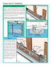
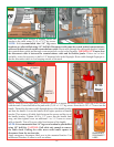
NOTE: The cable keeper must have a Min.
1/2” clearance between the section and vertical
track to function properly.
Push the spacer on to the roller shaft between the
bottom bracket and roller (see fig.1). Use an
additional spacer if needed to achieve min. 1/2”
clearance. If there is less than 1/2” clearance, loosen
the lag screws attaching the track to the wall to
provide additional clearance. After adjusting the track
for the 1/2” clearance re-tighten the lag screws.
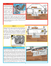
IMPORTANT! Right and left hand is always
determined from inside the building looking out.
Attach the right hand (Black) cable keeper assembly
to the bottom section directly above the bottom
bracket (see fig.2). Position the cable keeper assembly
so that it over hangs the edge of the section by 1/8”
(see fig.3). Fasten with (2) 1/4 x 11/16” self drilling
screws (wood doors will use (2) 1/4 x 1” lag screws).
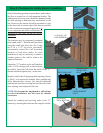
NOTE: It is recommended that wood doors be pre
drilled with an 1/8” pilot hole, prior to fastening.
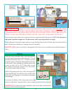
Repeat for the left hand
side (Red) cable keeper
assembly.
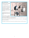
Once the cable keeper
assemblies are secured
to the section, place the
plastic sleeve over the
cable and then rotate the
arm upward and attach
it to the plastic sleeve.