


Photoelectric Safety Sensor
Installation Continued
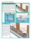
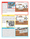
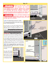
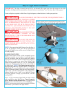
To locate the terminal block for the infrared sensor
sender/receiver wires, you must first move the right hand
gear assembly. Loosen the 3/8” square head bolt (refer
to Step 4.) and slide the gear assembly away from the
opener.
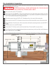
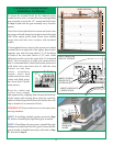
Uncoil wires from photoelectric sensors and route wires
up garage wall and along door header towards the right
side of the opener power head. Route wires behind
torque tube and tack wires in place with insulated
staples.
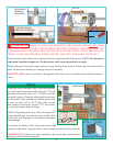
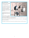
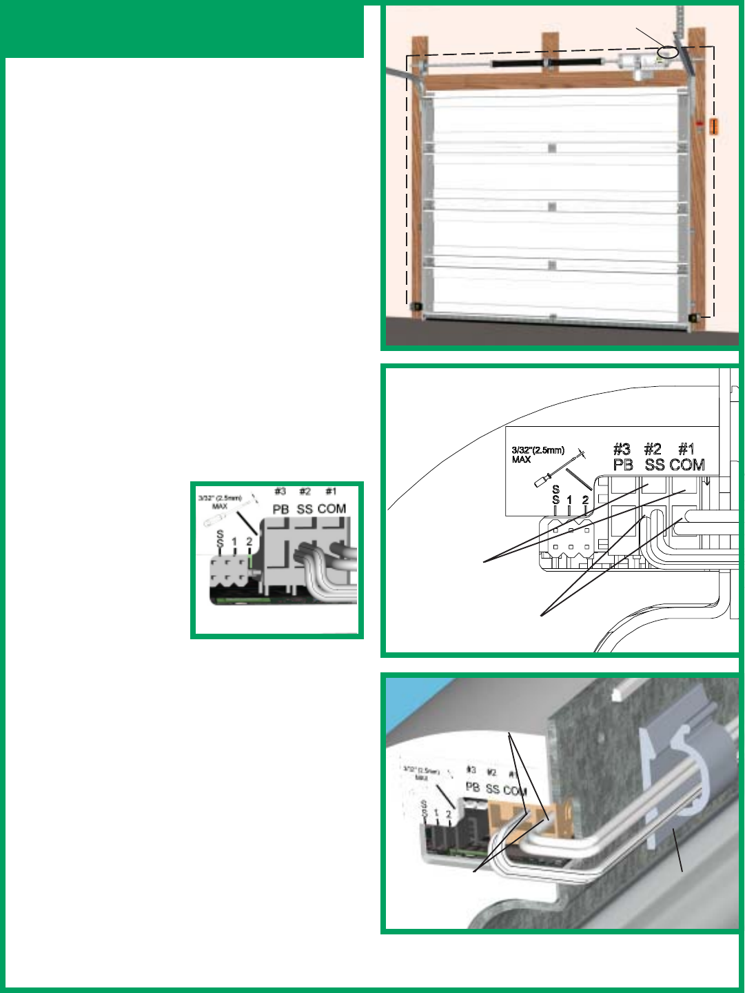
Connect photoelectric sensors to the opener power head
terminal block on right side of the opener power head.
Separate wire ends and strip about 1/2" of insulation
off each of the wire ends. Insert a 3/32" max. width
flathead screwdriver into the upper hole #1 of terminal
block. Twist screwdriver to open wire clamp in lower
hole #1 of terminal block. Insert both sender and receiver
solid white wires into lower hole #1 until the wires
bottom out and then
release screwdriver
tension. Insert both
sender and receiver wires
(white with black stripe)
into lower hole #2 by the
same process.
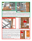
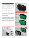
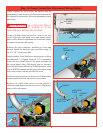
Keep the sender and
receiver wires straight
and organized by wrapping them around the backside
of the opener and securing them using the cord clip
(adhesive backed) provided.(Insure the surface the cord
clip is attached to is clean and oil free).
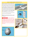
IMPORTANT! Keep sender/receiver wires away from
moving members.
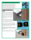
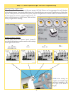
NOTE: If installing multiple openers proceed to Step
11, before reinstalling the right hand gear assembly.
NOTE: If installing only one opener, reinstall the right
hand gear assembly onto the drive gear. Ensure that the
gear assembly is installed correctly (refer back to Step
4). Proceed to Step 9.
CORD CLIP
INSERT
SENDER
WIRES
INSERT
RECEIVER
WIRES
RIGHT HAND SIDE
VIEW OF OPENER
INSERT SCREW-
DRIVER INTO
UPPER HOLES
INSERT WIRES INTO
LOWER HOLES
WIRE ROUTING
12