


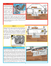
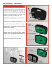
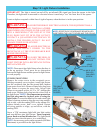
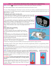
IMPORTANT! The light is turned on and off by an infrared (IR) signal sent from the opener to the light.
Therefore, the light must be mounted in a location where it can always “see” the front face of the opener.
Locate a duplex receptacle within line of sight of opener, when the door is in the open position.
WARNING TO AVOID THE RISK OF ELECTRICAL SHOCK, THIS EQUIPMENT HAS A
GROUNDING TYPE PLUG, THAT HAS A THIRD
(GROUNDING) PIN. THIS PLUG WILL ONLY FIT
INTO A GROUNDING TYPE OUTLET. IF THE
PLUG DOES NOT FIT INTO THE OUTLET,
CONTACT A QUALIFIED ELECTRICIAN TO
INSTALL THE PROPER OUTLET. DO NOT
CHANGE THE PLUG IN ANY WAY.
WARNING TO AVOID ELECTRICAL
SHOCK, DISCONNECT POWER TO THE
RECEPTACLE AT THE FUSE/BREAKER BOX
BEFORE PROCEEDING.
WARNING TO AVOID THE RISK OF
ELECTRICAL SHOCK, DO NOT INSTALL THE
LIGHT FIXTURE INTO A RECEPTACLE WITH A
METAL FACEPLATE.
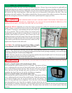
NOTE: Door must clear light fixture when the door is
in the up position. There must be no obstruction
between the light fixture and the opener for light fixture
to work properly.
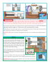
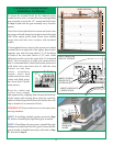
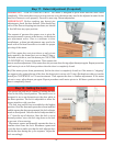
CEILING MOUNTING
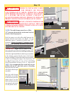
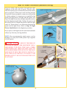
Remove the center screw in the receptacle cover.
Holding receptacle cover in place, insert light fixture
into the receptacle that has the ground hole farthest
from center screw hole. Remove center hole plug from
light fixture to expose the screw hole. Secure light
fixture to receptacle with a #6-32 x 3/4" phillips pan
head screw. Replace hole plug into the screw hole in
the light fixture. NOTE: For temperature protection,
the hole plug must be in place prior to using the
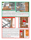
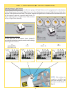
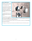
light fixture. Loosen the thumb screw and rotate light
fixture’s bottom section to align the receiving module,
side to side, with the sending LED on the opener. Re-
tighten thumb screw, don’t over tighten. Rotate
receiving module to align, up and down, with the
sending LED.
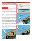
Screw a 75W maximum light bulb into light socket
and snap diffuser into light fixture. Turn receptacle
power back on at fuse/breaker box. The light should
blink one time when the power is re-established.
NOTE: An accessory power outlet receptacle (600 Watt
Maximum) is provided on the light fixture.
NOTE: RECEPTACLE COVER MUST BE INSTALLED
IN-BETWEEN THE LIGHT FIXTURE AND THE CEILING
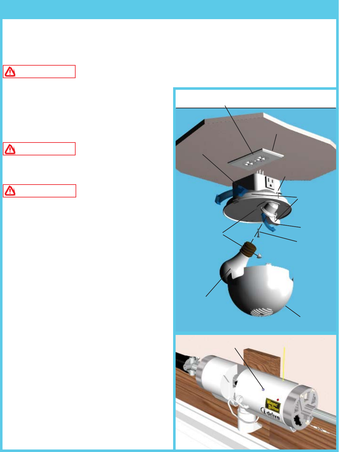
Step 12: Light Fixture Installation
16
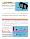
DUPLEX
RECEPTACLE
LIGHT FIXTURE
DIFFUSER
HOLE PLUG
#6-32 X 3/4”
PHILLIPS
PAN HEAD
SCREW
75W (MAX)
LIGHT BULB
(NOT IN-
CLUDED)
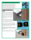
ALIGN
RECEIVING
MODULE
AIM AT
IR LED
SENDING IR
LED
THUMB
SCREW