


130
CHAPTER2 Dependence Functions
■ Setting Trace Trigger
When preselected conditions are met while monitoring the MCU bus operation, a trigger to start a trace can
be generated. This function is called a trace trigger.
To use the trace trigger function, specify the code (/CODE) and data access (/READ/WRITE).
Up to 4 trace triggers can be preset each for code attribute and data access attribute. However, actually, the
maximum number of trace triggers is determined as indicated below because common hardware is shared
with events.
Current trace trigger maximum count setting = 4 –
(current event count setting + current data watch break count setting)
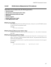
Table 2.3-7 shows the trace trigger setup conditions that can be defined:
For trace trigger setup, use the following commands:
• SET TRACETRIGGER : Trace trigger setup
• CANCEL TRACETRIGGER : Trace trigger deletion
• SHOW TRACE/STATUS : Trace setup display
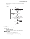
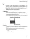
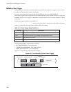
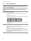
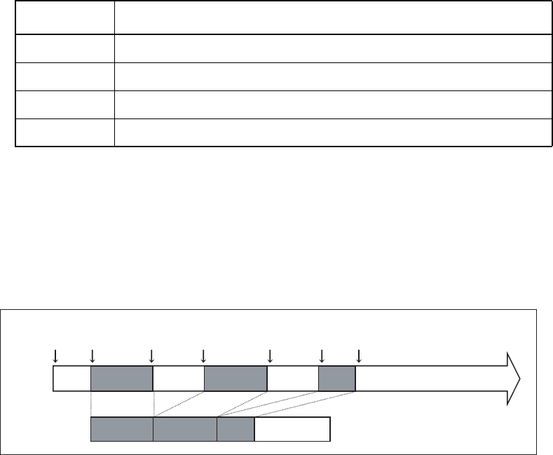
Figure 2.3-2 shows the operation of the trace sampling.
Figure 2.3-2 Trace Sampling Control (Trace Trigger)
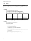
Table 2.3-7 Trace Trigger Setup Conditions
Condition Description
Address Memory location (Address bits can be masked.)
Data 32-bit data (Data bits can be masked.) Not applicable to codes
Access size Byte, halfword, or word
Status Code/data read or data write (selectable)
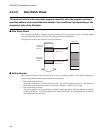
Start Resume Suspend Resume Suspend
Resume
Suspend
Program flow
Trace buffer