


www.gateway.com
7
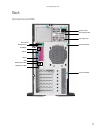
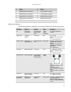
LED information
See the following table for a description of this server’s LEDs and the information they provide:
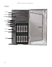
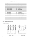
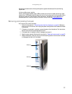
# Feature # Feature
1 SAS/SATA hard drive connector 0 6 I
2
C and system ID connector
2 SAS/SATA hard drive connector 1 7 I
2
C and system ID connector
3 SAS/SATA hard drive connector 2 8 Backplane power connector
4 SAS/SATA hard drive connector 3 9 Backplane SAS connector
5 SAS/SATA hard drive connector 4
LED Name Function Location Color Description
ID Aid in server
identification
Front panel and
back of system
board
Yellow
(front)
Blue (back)
On - Server identification
enabled
System Fault Visible fault
warning
Front panel Red Off - No fault
Blinking - Non-critical system
fault
On - Critical system fault
Hard drive tray Indicate drive
status and activity
On each hard drive
tray
Blue or Red Blue (On) - Hard drive okay
Blue (Blinking) - Hard drive
activity
Red (On) - Hard drive fault
Red (Blinking) - Hard drive
rebuilding
Off - No hard drive
LAN (front) Identify NIC status Front panel Blue On - LAN link for any NIC
Blinking - LAN activity for any
NIC
Off - No link for any NIC
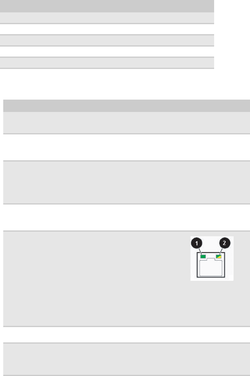
NIC status LEDs Identify NIC states Front panel and
back I/O panel
RJ-45 connectors
Green/
Yellow
LED 1 Green (On) - NIC linked
LED 1 Green (Blinking) - NIC
activity
LED 1 (Off) - No link
LED 2 Yellow (On) Link speed 1
Gbps
LED 2 Yellow (Off) - Link at other
speed
Power LED Identify the power
state of the system
Front panel Blue Off - Power is off (or S5)
On - Power is on (or S0)
Power supply
status LED
Identify power
supply fault
Power supply
module
Green or Red Green (On) - Power supply good
and receiving power
Red (On) - Power supply fault
Off - Power supply not receiving
power