


APPENDIX A: Server Specifications
80
Electronic specifications
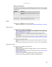
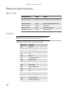
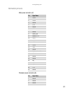
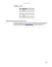
Memory map
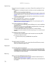
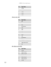
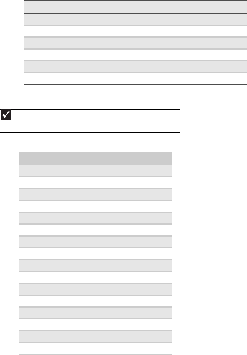
Interrupts
The following table reflects a typical configuration, but you can change these interrupts. Use this
information to determine how to program each interrupt.
Address Range (hex) Amount Function
0 to 07FFFFh 640 KB DOS region, base system memory
0A0000h to 0BFFFFh 128 KB Video or SMM memory
0C0000h and 0DFFFFh 128 KB Expansion card BIOS and buffer area
0E0000h to 0FFFFFh 128 KB System BIOS
0E0000h to 0EFFFFh 2 MB Extended system BIOS
FC000000h to FFFFFFFFh 64 MB PCI memory space
Important
If you disable an IDE controller to free the interrupt for that controller, you must
physically unplug the IDE cable from the system board. Simply disabling the drive by
configuring the BIOS option does not make the interrupt available.
ISA Interrupt Description
IRQ0 8254 timer
IRQ1 Keyboard controller
IRQ2 Cascade for IRQ9
IRQ3 Free
IRQ4 Serial port
IRQ5 Hot-plug SCSI controller
IRQ6 Diskette controller
IRQ7 Free
IRQ8 Real-time clock
IRQ9 Generic, Option for SCI
IRQ10 VGA
IRQ11 USB
IRQ12 Mouse controller
IRQ13 Numeric data processor
IRQ14 Primary IDE controller
IRQ15 Secondary IDE controller