


CHAPTER 6: Troubleshooting
68
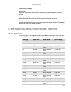
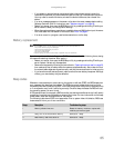
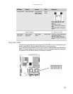
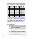
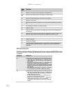
The eight diagnostic LEDs are divided into two groups. LEDs from CR16-CR19 comprise one group,
and LEDs from CR20-CR24 comprise the other group. The two groups represent the two digits of
the hex code. The CR16-CR19 group stands for the first digit and the CR20-CR24 group stands for
the second.
In determining the code, Off = 0 and On = 1. Based on this, you can determine the corresponding
hex code. Then, by checking “POST code checkpoints” on page 68, “Bootblock initialization code
checkpoints” on page 71, “Bootblock recovery code checkpoints” on page 71, “DIM code
checkpoints” on page 72, and “ACPI runtime checkpoints” on page 73, you can find out where an
error is taking place.
For example, if a hex code of 0B is indicated, you can detemine that the server cannot detect the
PS/2 mouse. You can then take measures, such as reinserting the mouse, to solve the problem.
All LEDs are cleared and restored to normal status after the server is power cycled.
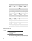
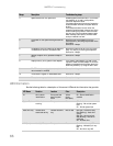
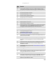
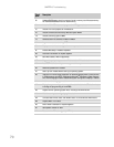
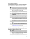
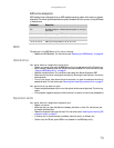
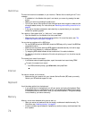
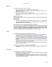
POST code checkpoints
The following table shows the checkpoints, LED codes, and task description of events that may
occur during the POST portion of the BIOS:
Check
point
Description
03 Disable NMI, Parity, video for EGA, and DMA controllers. Initialize BIOS, POST, Runtime
data area. Also initialize BIOS modules on POST entry and GPNV area. Initialized CMOS
as mentioned in the Kernel Variable “wCMOSFlags.”
04 Check CMOS diagnostic byte to determine if battery power is OK and CMOS checksum
is OK. Verify CMOS checksum manually by reading storage area. If the CMOS
checksum is bad, update CMOS with power-on default values and clear passwords.
Initialize status register A.
Initialize data variables that are based on CMOS setup questions. Initialize both the
8259 compatible PICs in the system.
05 Initialize the interrupt controller in hardware (generally PIC) and interrupt vector
table.
06 Do R/W test to CH-2 count reg. Initialize CH-0 as system timer. Install the POSTINT1Ch
handler. Enable IRQ-0 in PIC for system timer interrupt.
Trap INT1Ch vector to “POSTINT1ChHandlerBlock.”
Hex
Code
CR24 CR23 CR22 CR21
Hex
Code
CR19 CR18 CR17 CR16
8 4 2 1
8 4 2 1
0
0 0 0 0
0
0 0 0 0
1
0 0 0 1
1
0 0 0 1
2
0 0 1 0
2
0 0 1 0
3
0 0 1 1
3
0 0 1 1
4
0 1 0 0
4
0 1 0 0
5
0 1 0 1
5
0 1 0 1
6
0 1 1 0
6
0 1 1 0
7
0 1 1 1
7
0 1 1 1
8
1 0 0 0
8
1 0 0 0
9
1 0 0 1
9
1 0 0 1
A
1 0 1 0
A
1 0 1 0
B
1 0 1 1
B
1 0 1 1
C
1 1 0 0
C
1 1 0 0
D
1 1 0 1
D
1 1 0 1
E
1 1 1 0
E
1 1 1 0
F
1
1
1 1
F
1 1 1 1