CHAPTER 4: Installing Components
50
11 Insert the new system board into the chassis, align it with the six retaining standoffs, then
slide the board toward the back of the case so the board is held by the standoffs.
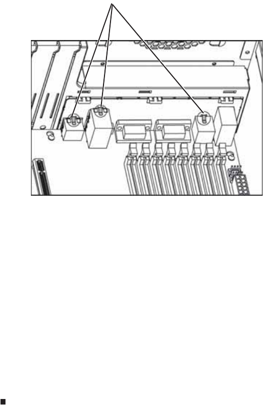
Make sure that the three clips marked in the following illustration end up on top of the
management port, the dual NIC connector, and the dual USB port. Otherwise the system
board cannot be installed correctly.
12 Tighten the two system board thumbscrews you loosened in Step 8.
13 Connect the cables you removed in Step 7
14 Reinstall the memory by following the instructions in “Installing memory” on page 33.
15 Replace the processor(s) and heatsink(s) by following the instructions in “Replacing or
adding a processor” on page 40.
16 Reinstall the PCI expansion cards by following the instructions in “Installing and removing
PCI expansion cards” on page 37.
17 Return the chassis to its upright position, if necessary.
18 Close the server case by following the instructions in “Closing the server case” on page 26.
19 Restart your server, then press F2 at any time after you see the LEDs on your keyboard
flash or turn off. The BIOS Setup utility opens.
20 Check BIOS settings to make sure that they detect the server’s new hardware, then save
your changes (if any) and close the BIOS Setup utility.
21 If your server does not start after installing the new system board, contact Gateway
Customer Care. For more information, see “Getting Help” on page 8.
Clips


