


www.gateway.com
67
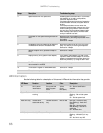
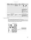
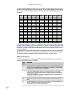
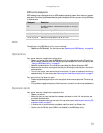
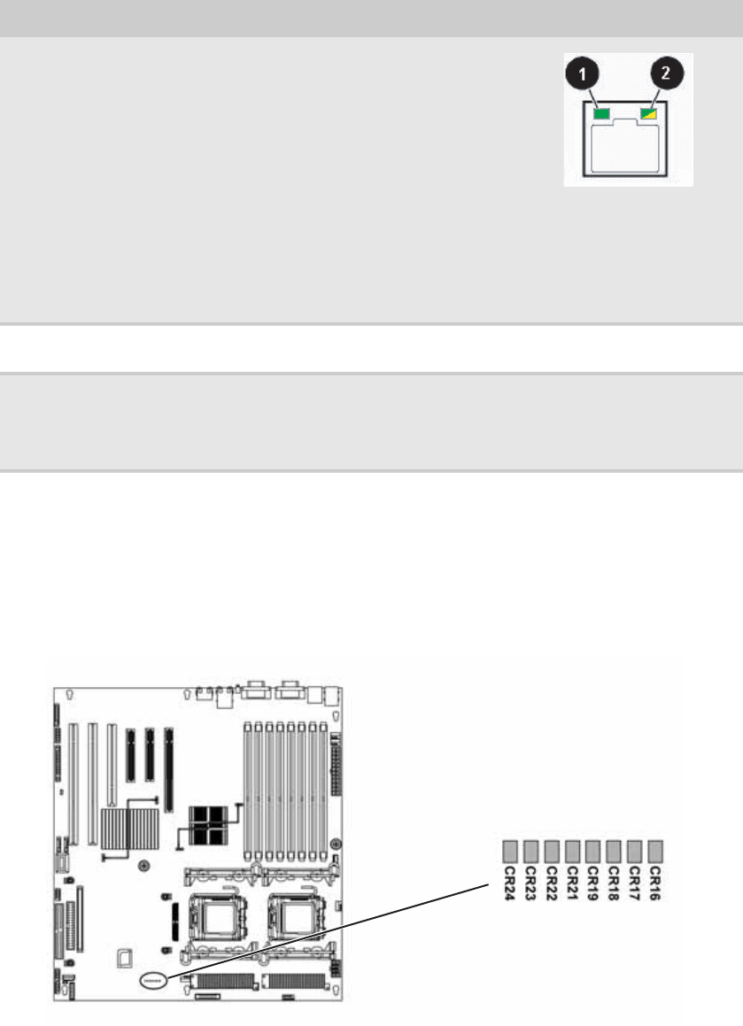
Diagnostic LEDs
This system board provides a set of eight diagnostic (Port 80) LEDs. If you are troubleshooting your
system, these LEDs can help you determine where errors are taking place.
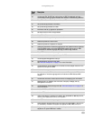
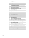
If you are experiencing problems with your server, open the case and check these LEDs (CR16 to
CR24) on the system board, then check the tables on the following pages to determine the problem.
The location of Port 80 LEDs is shown in the following illustration:
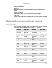
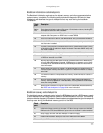
NIC status LEDs Identify NIC states Front panel and
back I/O panel
RJ-45 connectors
Green/
Yellow
LED 1 Green (On) - NIC linked
LED 1 Green (Blinking) - NIC
activity
LED 1 (Off) - No link
LED 2 Yellow (On) Link speed 1
Gbps
LED 2 Yellow (Off) - Link at other
speed
Power LED Identify the power
state of the system
Front panel Blue Off - Power is off (or S5)
On - Power is on (or S0)
Power supply
status LED
Identify power
supply fault
Power supply
module
Green or Red Green (On) - Power supply good
and receiving power
Red (On) - Power supply fault
Off - Power supply not receiving
power
LED Name Function Location Color Description