


Model G0746/G0749 (Mfg. Since 3/13)
-19-
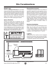
Connection Type
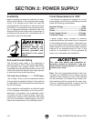
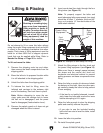
Figure 10. Typical setup of a permanently
connected machine.
Power
Source
Locking
Disconnect Switch
Machine
Ground
Ground
ConduitConduit
A permanently connected (hardwired) power sup-
ply is typically installed with wires running through
mounted and secured conduit. A disconnecting
means, such as a locking switch (see following
figure), must be provided to allow the machine
to be disconnected (isolated) from the power
supply when required. This installation must be
performed by an electrician in accordance with all
applicable electrical codes and ordinances.
Serious injury could occur if you connect
the machine to power before completing the
setup process. DO NOT connect to power
until instructed later in this manual.
Grounding Instructions
In the event of a malfunction or breakdown,
grounding provides a path of least resistance
for electrical current to reduce the risk of electric
shock. A permanently connected machine must
be connected to a grounded metal permanent wir
-
ing system; or to a system having an equipment-
grounding conductor. All grounds must be verified
and rated for the electrical requirements of the
machine. Improper grounding can increase the
risk of electric shock!
Extension Cords
Since this machine must be permanently con-
nected to the power supply, an extension cord
cannot be used.
This sub-section is only provided for troubleshoot-
ing. If you discover that the lathe will not operate,
or that the spindle runs backwards, the lathe may
be wired out of phase.
Correcting phase polarity requires reversing the
positions where two incoming power source wires
are connected. Due to the high voltage and risk of
serious shock involved, we strongly recommend
this procedure only be done by an electrician or
qualified service personnel.
To correct the phase polarity of the incoming
power supply:
1. DISCONNECT MACHINE FROM POWER!
2. Open electrical box located at back of
machine.
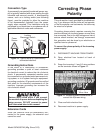
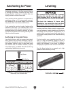
3. Swap the incoming L1 and L2 wire positions
on the terminals shown in Figure 11.
Correcting Phase
Polarity
3. Close and latch electrical box.
4. Reconnect machine to power supply.
Figure 11. Swapping power connections to
correct out-of-phase wiring.
Swap Any Two
Wires Here