


-84-
Model G0746/G0749 (Mfg. Since 3/13)
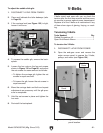
Replacing Brake
1. DISCONNECT LATHE FROM POWER!
2. Open the end-gear cover.
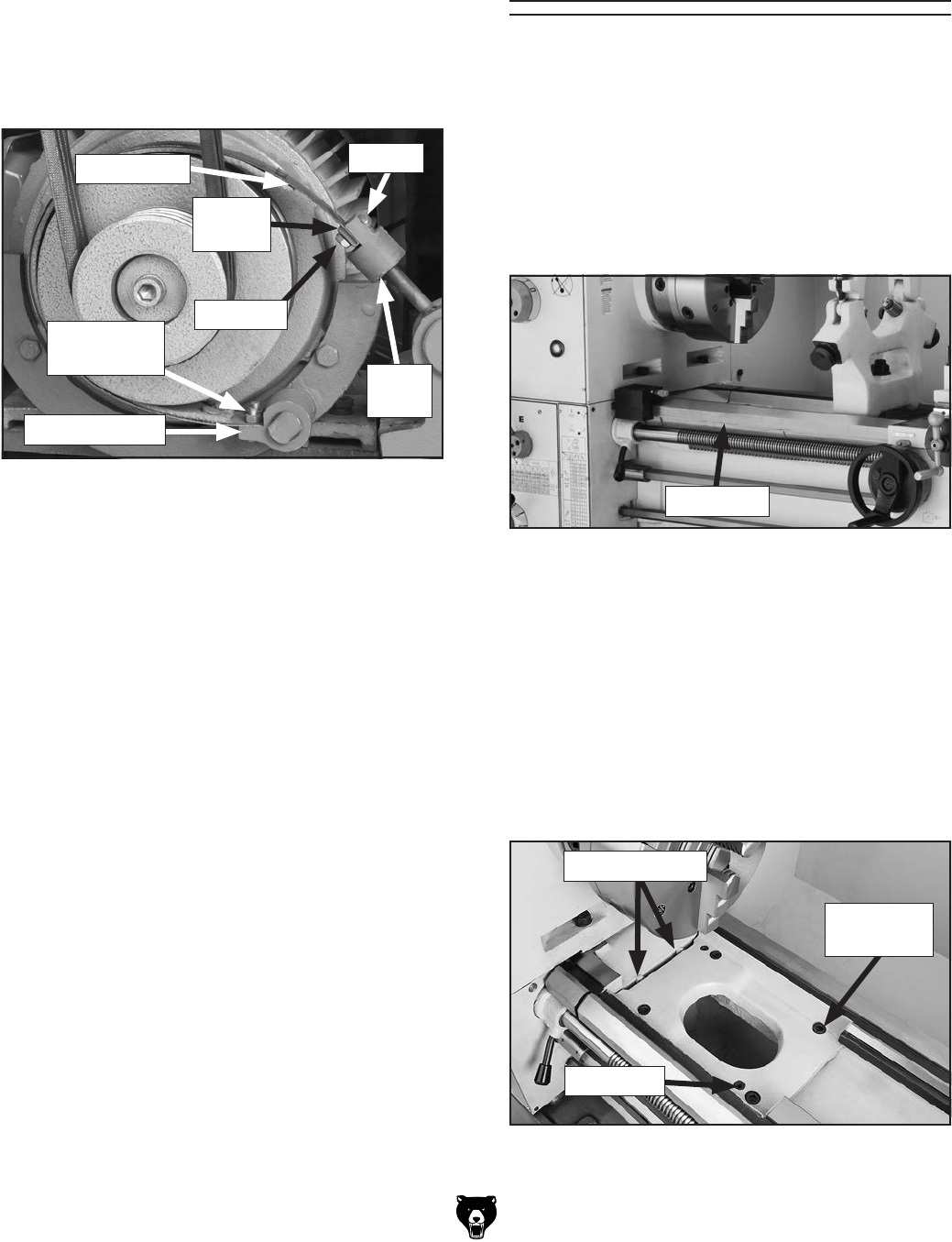
3. Remove the hex nuts and screws that attach
the brake band to the pedal bolt and end
block shown in Figure 138.
Figure 138. Brake replacement components.
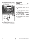
4. Remove the hex nuts and screws that attach
the lower part of the brake band to the brake
bracket (see Figure 138), then remove the
brake band.
5. Install the new brake band on the brake brack-
et with the screws and nuts you removed in
Step 4.
6. Pull the brake band over the drum and attach
it to the pedal bolt with the screws, end block,
and hex nuts removed in Step 3.
Refer to Adjusting Brake subsection to ten-
sion the brake.
Screws
Hex Nuts
End
Block
Brake Band
Hex Nuts &
Screws
Pedal
Bolt
Tools Needed: Qty
Open-End Wrench 14mm .................................. 1
Hex Wrench 10mm ............................................ 1
Heavy Dead Blow Hammer ............................... 1
Slide Hammer w/M8-1.25 Handle End Thread . . 1
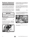
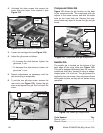
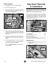
Gap Removal
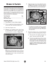
1. Remove the four gap-bed cap screws, shown
in Figure 140.
The gap insert directly under the spindle (see
Figure 139) can be removed to create additional
space for turning large diameter parts.
The gap insert was installed, then ground flush
with the bed at the factory to ensure a precision
fit and alignment. Therefore, if the gap insert is
removed, it may be difficult to re-install with the
same degree of accuracy.
Figure 139. Gap insert.
Gap Insert Removal
& Installation
Figure 140. Fasteners holding gap in place.
Gap Insert
Gap-Bed
Cap Screw
Dowel Pin
Pre-Load Bolts
Brake Bracket