


-62-
Model G0746/G0749 (Mfg. Since 3/13)
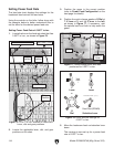
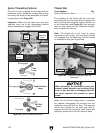
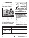
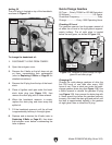
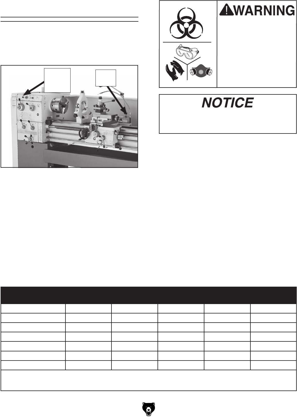
When the coolant pump is turned ON, fluid is
delivered through the nozzle attached to the car-
riage. The flow is controlled by the valve lever at
the base of the nozzle (see Figure 100).
To use the coolant system on your lathe:
1. Make sure the coolant tank is properly ser-
viced and filled with the appropriate fluid, and
that you are wearing the necessary personal
protection equipment.
2. Position the coolant nozzle for your opera-
tion.
3. Use the coolant pump switch on the control
panel to turn the pump ON.
4. Adjust the flow of coolant by using the valve
lever near the base of the nozzle hose.
Important: Promptly clean any splashed fluid
from the floor to avoid a slipping hazard.
Coolant System
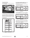
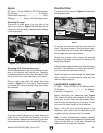
Figure 101. Coolant selection table.
Workpiece Dry
Water
Soluble Oil
Synthetic
Fluids
Sulferized Oil Mineral Oil
Aluminum X X
Brass X X X
Bronze X X X X
Cast Iron X
Low Carbon Steel X X
Alloy Metals X X X X
Stainless Steel X X X X
General Note: Cutting fluids are used for heavy-duty lathe operations and production turning. Oil-water emulsions and synthetic
cutting fluids are the most common for typical lathe operations. Sulferized oils often are used for threading. For small projects,
spot lubrications can be done with an oil can or brush, or omitted completely.
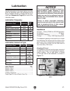
Running the pump without adequate fluid in
the coolant tank may permanently damage
it, which will not be covered under warranty.
BIOLOGICAL & POISON
HAZARD!
Use the correct person-
al protection equipment
when handling coolant.
Follow federal, state,
and fluid manufacturer
requirements for proper
disposal.
Always use high quality coolant and follow the
manufacturer's instructions for diluting. The quick
reference table shown in Figure 101 can help you
select the appropriate fluid.
Refer to Coolant System Service on Page 72
for detailed instructions on how to add or change
fluid. Check the coolant regularly and promptly
change it when it becomes overly dirty or rancid,
or as recommended by the fluid manufacturer.
Figure 100. Coolant flow controls.
Valve
Lever
Coolant
Pump
Switch