


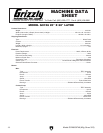
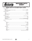
Model G0746/G0749 (Mfg. Since 3/13)
-5-
Controls &
Components
Refer to Figures 3–8 and the following descrip-
tions to become familiar with the basic controls of
this lathe.
Many of the controls will be explained in greater
detail later in this manual.
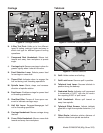
Headstock
A. Spindle Speed Range Lever: Selects one of
three spindle speed ranges.
B. Headstock Feed Direction Lever: Controls
rotation direction of leadscrew and feed rod.
C. Spindle Speed Lever: Selects one of five
different spindle speeds within the selected
speed range.
D. Spindle Speed Chart: Shows how to posi-
tion the spindle speed lever and spindle
range lever to set each of the 15 available
spindle speeds.
E. Thread and Feed Chart: Shows how to
arrange gearbox controls for different thread-
ing or feeding options.
F. Quick-Change Gearbox Levers and Dial:
Controls leadscrew and feed rod speed for
threading and feeding operations.
G. Leadscrew Feed Rod Selection Lever:
Enables leadscrew or feed rod.
Figure 3. Headstock controls.
B
E
C
A
F
D
G
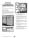
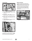
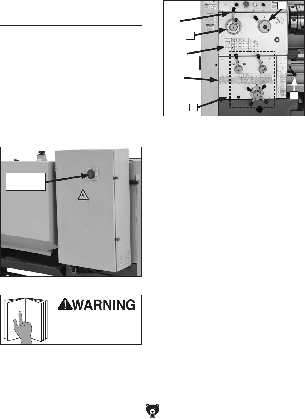
Master Power Switch
The rotary switch shown in Figure 2 toggles
incoming power ON and OFF to the lathe controls.
As a safety feature, it also prevents the electrical
cabinet door from being opened when the switch
is ON.
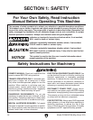
To reduce your risk of
serious injury, read this
entire manual BEFORE
using machine.
Figure 2. Location of the main power switch.
Main Power
Switch