


-56-
Model G0746/G0749 (Mfg. Since 3/13)
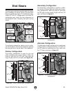
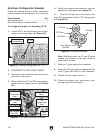
End-Gear Configuration Example
Follow the example below to better understand
how to configure the end gears for inch threading.
Tools Needed Qty
Hex Wrench 6mm .............................................. 1
Open-End Wrench or Socket 24mm ................. 1
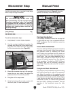
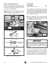
Arm-Support
Hex Nut
36T Gear
72T Gear
Z1 Gear
Z2 Gear
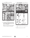
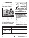
Figure 85. End gear placement.
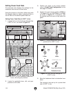
5. Slowly let the gears pivot down until they rest
against the V-belt guard (see Figure 84).
6. Slide the Z2 gear out on its shaft so the
outer Z2 gear meshes with the 36T change gear
(see Figure 85).
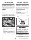
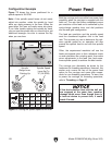
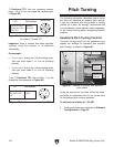
To configure end gears for threading 16 TPI:
1. Locate 16 TPI and the primary gear configu-
ration on the thread chart (see Figure 83).
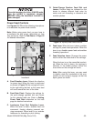
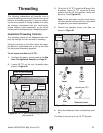
2. DISCONNECT LATHE FROM POWER!
3. Remove the cap screw that secures the end-
gear cover, then open it.
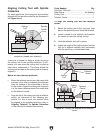
4. While holding the 36T and 72T change gears,
loosen the arm support hex nut (see Figure
84).
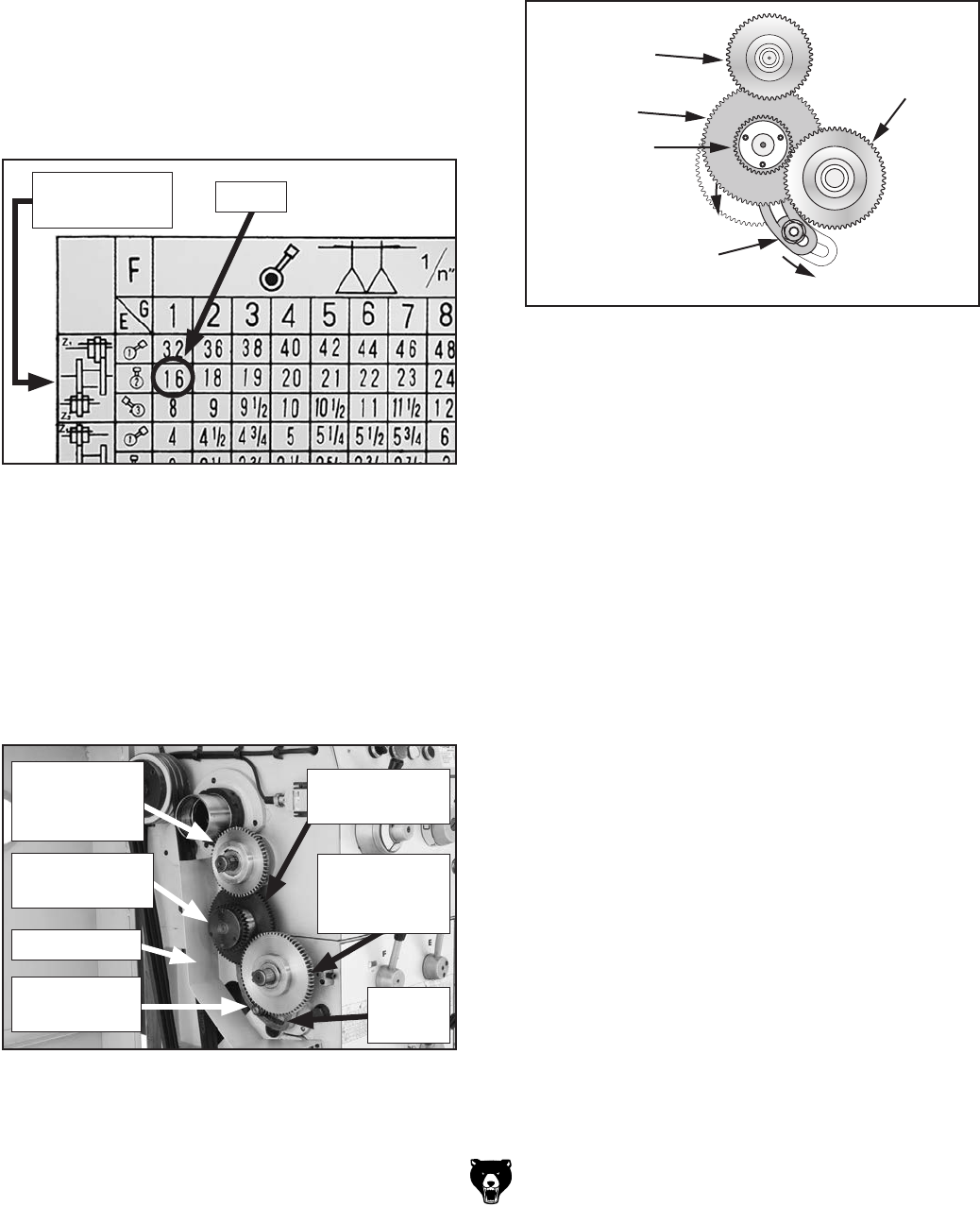
Figure 84. Arm support and gear locations.
72T Change
Gear
Z2
Combination
Gear
Z1
Combination
Gear
36T Change
Gear
Arm Support
Hex Nut
Arm
Support
V-Belt Guard
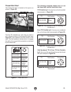
7. Slide the Z1 gear against the headstock.
8. Rotate the 72T gear up so it meshes with the
inner Z1 gear with 0.002" to 0.004" backlash.
9. Tighten the arm support hex nut.
10. Close the end-gear cover and secure it with
the cap screw removed earlier.
Note: Steel balls under the Z1 and Z2 gears
engage with detents on the gear shafts to
secure them in place.
Figure 83. Locating change gears for 16 TPI.
16 TPI
Primary Gear
Configuration