


-72-
Model G0746/G0749 (Mfg. Since 3/13)
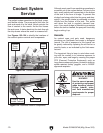
The coolant system consists of a fluid tank, pump,
and flexible nozzle. The pump pulls fluid from the
tank and sends it to the valve, which controls the
flow of coolant to the nozzle. As the fluid leaves
the work area, it drains back into the tank through
the chip drawer where the swarf is screened out.
Use Figures 123–124 to identify the locations of
the coolant system controls and components.
Although most swarf from machining operations is
screened out of the coolant before it returns to the
tank, small particles will accumulate in the bottom
of the tank in the form of sludge. To prevent this
sludge from being pulled into the pump and dam-
aging it, the pump’s intake is positioned a couple
inches from the bottom of the tank. This works
well when the tank is regularly cleaned; how-
ever, if too much sludge is allowed to accumulate
before the tank is cleaned, the pump will inevitably
begin sucking it up.
Hazards
As coolant ages and gets used, dangerous
microbes can proliferate and create a biological
hazard. The risk of exposure to this hazard can
be greatly reduced by replacing the old fluid on a
monthly basis, or as indicated by the fluid manu-
facturer.
The important thing to keep in mind when work-
ing with the coolant is to minimize exposure to
your skin, eyes, and lungs by wearing the proper
PPE (Personal Protective Equipment), such as
long-sleeve waterproof gloves, protective clothing,
splash-resistant safety goggles, and a NIOSH-
approved respirator.
Coolant System
Service
BIOLOGICAL & POISON
HAZARD!
Use the correct person-
al protection equipment
when handling coolant.
Follow federal, state,
and fluid manufacturer
requirements for proper
disposal.
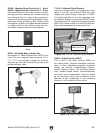
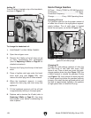
Figure 123. Coolant controls.
Coolant
Pump
Switch
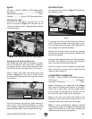
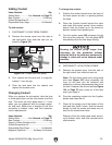
Figure 124. Additional coolant components.
Chip Drawer
Drain Tube
Pump & Tank
(Inside Cabinet)
Valve
Lever