


Model G0746/G0749 (Mfg. Since 3/13)
-55-
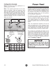
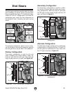
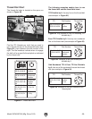
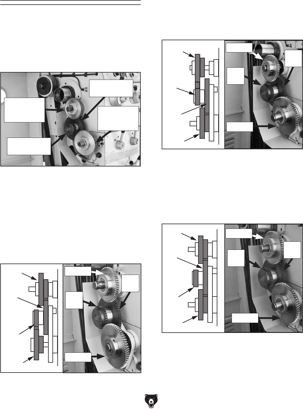
The end gears must be correctly setup for power
feed, threading, and pitch turning. Use the photo
below to identify the upper Z1 combination gear,
middle 36T and 72T change gears, and lower Z2
combination gear, which are also referenced on
the headstock feed, threading, and pitch turning
charts.
End Gears
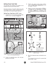
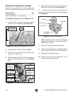
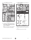
Secondary Configuration
The secondary configuration is used for a differ-
ent range of threads and feed rates than the pri-
mary configuration. Mesh the large Z1 gear with
the 36T gear and the small Z2 gear with the 72T
gear, as shown in Figure 81.
Figure 81. Secondary change gear
configuration.
Z1
Z2
72T
36T
Z1
Z2
72T
36T
Z1
Z2
72T
36T
Alternate
#2
#1
72T
Gear
Z1 Gear
36T
Gear
Z1 Gear
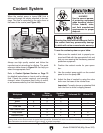
Alternate Configuration
The alternate end gear configuration is used when
cutting modular or diametral pitches. The small Z1
and Z2 gears are positioned so they mesh with
the 72T gear, as shown in Figure 82.
Figure 82. Diametral and modular change gear
configuration.
Z1
Z2
72T
36T
Z1
Z2
72T
36T
Z1
Z2
72T
36T
Alternate
#2
#1
72T
Gear
Z1 Gear
36T
Gear
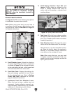
Figure 79. Change gear identification.
36T Change
Gear
72T Change
Gear
Z2
Combination
Gear
Z1
Combination
Gear
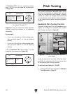
Primary Configuration
The primary configuration is used for inch and
metric threading and power feeding. Mesh the
small Z1 gear with the 72T gear, and mesh the
large Z2 gear with the 36T gear (see Figure 80).
Figure 80. Primary change gear configuration.
Z1
Z2
72T
36T
Z1
Z2
72T
36T
Z1
Z2
72T
36T
Alternate
#2
#1
72T
Gear
Z1 Gear
36T
Gear
Z2 Gear
The following subsections explain how to config-
ure the end gears, which are accessed by opening
the end-gear cover on the side of the headstock.
Z1 Gear