


-52-
Model G0746/G0749 (Mfg. Since 3/13)
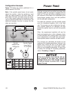
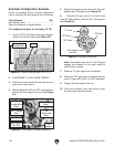
Configuration Example
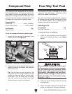
Both the carriage and cross slide have power feed
capability when the carriage is engaged with the
feed rod. The rate that these components move
per revolution of the feed rod is controlled by the
quick-change gearbox lever and dial positions
and the end gear configuration.
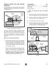
The feed per revolution and the spindle speed
must be considered together—this is the feed
rate. The sources you use to determine the opti-
mum spindle speed for an operation will also
provide the optimal feed to use with that spindle
speed.
Often, the experienced machinist will use the
feeds and speeds given in their reference charts
or web calculators as a starting point, then make
minor adjustments to the feed rate (and some-
times spindle speed) to achieve the best results.
The carriage can alternately be driven by the
leadscrew for threading operations. However, this
section only covers the use of the power feed
option for the carriage and cross slide compo-
nents for non-threading operations. To learn how
to power the carriage for threading operations,
refer to Threading on Page 57.
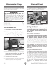
Power Feed
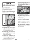
If the feed selection lever and the half nut
are engaged at the same time, machine
damage could occur. Even though there is
a lock-out device to prevent this, it could
break if forced.
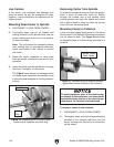
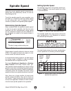
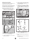
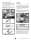
Figure 73 shows the levers positioned for a
spindle speed of 24 RPM.
Note: If the spindle speed levers do not easily
adjust into position, rotate the spindle by hand
while you apply pressure to the lever. When the
gears align, the lever will easily move into place.
If you have trouble rotating the spindle by hand,
you can use the spindle key or a chuck key to get
additional leverage—be sure to remove the key
when you are done.
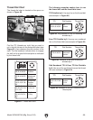
Figure 73. Setting the spindle speed to 24 RPM.
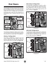
Spindle Speed
Lever Set To
“E” (24 RPM)
Spindle
Range Lever
Pointing Up
E
Spindle
Speed Lever
Spindle Range
Lever
A B C D
290845 130 55
75 33175395
240 105 455451600
1150
X
min
24
E