


-60-
Model G0746/G0749 (Mfg. Since 3/13)
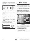
1
⁄2 Fractional TPI: Use any opposing number
pairs—1/3 or 2/4 on the thread dial (see example
in Figure 95).
1
2
3
4
Thread Dial
TPI Dial Number
1½,2½,3½,4½,
5½,6½,9½,10½,
11½,13½
Position
1,3 or 2,4
Figure 95. Example of opposing number groups
for cutting
1
⁄2 thread TPI.
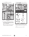
1
⁄4 or
3
⁄4 Fractional TPI: Use position 1 on the
thread dial (see example in Figure 96).
1
2
3
4
Thread Dial
TPI Dial Number
1¼,1¾,2¼,2¾,
3¼,4¾,5¼,5¾,
6¾
Position
1 Only
Figure 96. Example of
1
⁄4 or
3
⁄4 fractional TPI.
Important: Once a number has been selected,
continue using that number or its odd/even
counterpart.
For example:
• If you use 1 during the first threading pass,
then you must select 1 or 3 for all following
passes.
• If you use 2 during the first threading pass,
then you must select 2 or 4 for all following
passes.
The following subsection describes how to set up
the lathe for diametral or modular pitch turning.
If you are unfamiliar with the process of turning
pitches on a lathe, we strongly recommend that
you read books, review industry trade magazines,
or get formal training before attempting specific
projects.
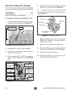
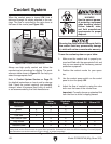
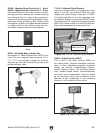
Headstock Pitch Turning Controls
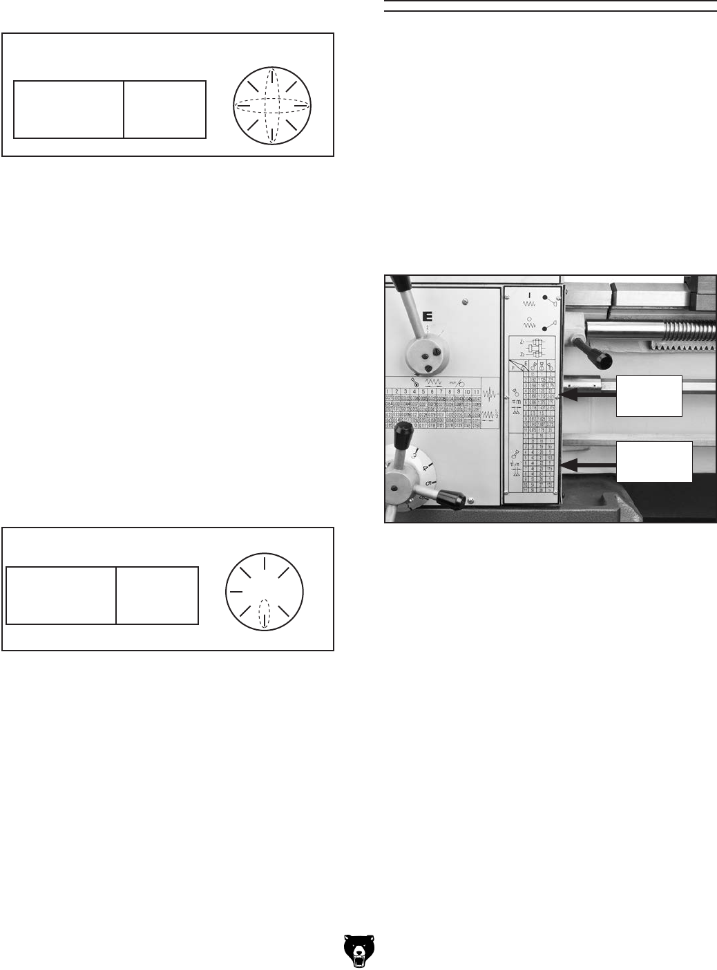
The pitch turning charts on the headstock face
display the settings for diametral and modular
pitch turning, as shown in Figure 97.
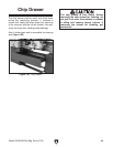
Pitch Turning
Using the controls on the lathe, follow the exam-
ple below to understand how to set up the lathe
for the desired pitch turning operation.
To set levers and dials for 1.25 MP:
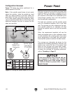
1. Configure the gears as instructed in Alternate
Configuration on Page 55.
Figure 97. Location of modular and diametral
pitch charts.
Diametral
Pitches
Modular
Pitches