


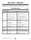

Model G0746/G0749 (Mfg. Since 3/13)
-79-
The goal of adjusting the gib screws is to remove
sloppiness or "play" from the ways without over-
adjusting them to the point where they become
stiff and difficult to move.
In general, loose gibs cause poor finishes and
tool chatter; however, over-tightened gibs cause
premature wear and make it difficult to turn the
handwheels.
Gib AdjustmentLeadscrew End-Play
Adjustment
After a long period of time, you may find that the
leadscrew develops excessive end play. This
lathe is designed so that end play can be removed
with a simple adjustment.
Items Needed Qty
Spanner Wrench................................................ 1
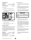
To remove leadscrew end play:
1. DISCONNECT LATHE FROM POWER.
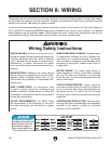
2. Loosen the outer spanner nut (see Figure
128).
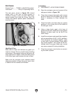
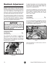
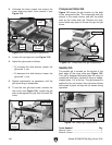
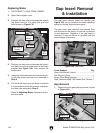
The cross-slide and compound slide on this lathe
each use a long steel wedge called a gib that
is positioned between the component and its
dovetailed-ways. A gib screw at one end moves
the gib. Depending upon which direction the
gib moves, the space between the sliding ways
increases or decreases to control the rigidity of
the cross slide and compound slide.
Before adjusting the gibs, loosen the locks for the
devices so the gibs can slide freely during adjust-
ment, then lubricate the ways.
The gib adjustment process usually requires
some trial-and-error. Repeat the process as nec-
essary until you find the best balance between
loose and stiff movement. Most machinists find
that the ideal gib adjustment is one where a small
amount of drag or resistance is present, yet the
handwheels are still easy to move.
Tools Needed Qty
Standard Screwdriver #2 ................................... 1
Slotted Screwdriver #2 ...................................... 1
Cross Slide Gib
Make sure the ways and leadscrew have been
cleaned and re-lubricated before beginning any
adjustments. Refer to Ball Oiler Lubrication on
Page 70 for instructions and lubricant specifica-
tions.
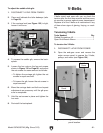
To adjust the cross slide gib:
1. DISCONNECT LATHE FROM POWER!
3. Place a dial indicator on the end of the
leadscrew.
4. Rotate the carriage handwheel to move the
carriage toward the tailstock, then tighten
the inner spanner nut (see Figure 128) until
there is 0.001"–0.002" of end play.
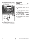
5. Tighten the outer spanner nut until it is snug
against the inner spanner nut to secure the
setting.
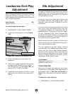
Leadscrew
Figure 128. Leadscrew and spanner nuts.
Outer Spanner Nut
Inner Spanner Nut