


Model G0746/G0749 (Mfg. Since 3/13)
-83-
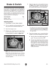
As the brake lining wears, the foot pedal develops
more travel. If the brake band is not adjusted to
compensate for normal wear, the limit switch will
still turn the lathe OFF, but the spindle will not
stop as quickly. It is especially important that the
brake is kept properly adjusted so you can quickly
stop the spindle in an emergency.
Tools Needed: Qty
Wrench 17mm.................................................... 1
Hex Wrench 8mm .............................................. 1
Adjusting Brake
1. DISCONNECT LATHE FROM POWER!
2. Put on a respirator and eye protection to pro-
tect yourself from hazardous brake dust.
3. Open the end-gear cover.
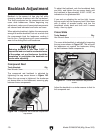
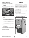
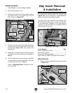
4. Measure the remaining brake band lining
at the thinnest point, which is usually at the
8 o'clock position, as shown in Figure 136.
Brake & Switch
Note: When the brake band is new, the lining
is approximately 4mm thick. If the lining thick-
ness wears to 1m or less, the brake band
must be replaced.
Figure 136. Minimum brake belt thickness.
1mm
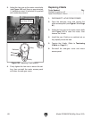
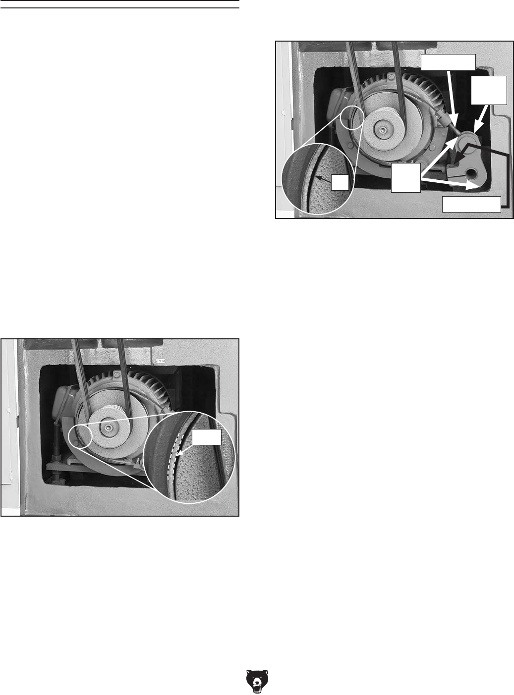
5. Adjust the hex nuts on the pedal bolt shown
in Figure 137 to tighten the brake band so
there is approximately
1
⁄8" clearance between
the pad and hub around its circumference.
Figure 137. Brake tensioning components.
Pedal Bolt
Hex
Nuts
Pedal
Lever
—If additional brake band tension is needed,
loosen the cap screw shown in Figure 137,
pivot the pedal lever to the right and tighten
the cap screw.
6. Close the end-gear cover, connect the lathe
to power, then test the brake pedal as follows:
a. Start the lathe, then lightly press the foot
pedal. The motor should shut OFF.
b. Push the foot pedal down further to stop
spindle rotation. You should not need to
press the pedal down completely to stop
the spindle, nor should the spindle keep
rotating. If either symptom occurs, repeat
Steps 5–6 until you are satisfied with the
brake performance.
Cap Screw
1
⁄8"