


-80-
Model G0746/G0749 (Mfg. Since 3/13)
Compound Slide Gib
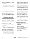
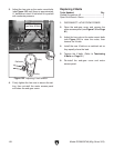
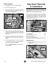
Figure 131 shows the gib location on the back
of the compound slide. The compound slide gib
adjusts in the same manner and with the same
tools as the cross slide gib. Remove the com-
pound slide way wiper to access the gib and gib
screw.
3. Loosen the carriage lock (see Figure 129).
4. Adjust the gib screw as follows:
—To increase the slide tension, tighten the
gib screw
1
⁄8 turn.
—To decrease the slide tension, loosen the
gib screw
1
⁄8 turn.
5. Repeat adjustments as necessary until the
gib screw drag is acceptable.
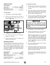
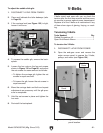
6. To set the rear gib stop screw, remove the
rear cover (see Figure 130), tighten the gib
stop screw against the gib, then re-install the
cover.
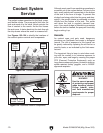
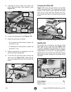
Figure 129. Cross slide gib components.
Saddle Gib
Figure 131. Compound slide gib components.
Gib
Screw
Slide Lock
2. Unthread the three screws that secure the
cross slide way wiper, then remove it (see
Figure 129.
Gib
Screw
Figure 130. Cross slide gib stop screw.
Rear Cover
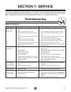
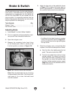
The saddle gib is located on the bottom of the
back edge of the cross slide (see Figure 132).
This gib is designed differently than the cross or
compound slide gibs. Instead of being a wedge-
shaped plate, it is a flat bar. The gib pressure is
applied by four set screws. Hex nuts secure these
set screws in place, so they will not loosen during
operation.
Figure 132. Saddle gib components.
Set Screws & Hex Nuts
Tools Needed Qty
Wrench 7mm ..................................................... 1
Wrench 10mm ................................................... 1
Gib
Way Wiper
Gib
Carriage
Lock
Gib
Gib Stop
Screw
Gib
Way Wiper
Screws