


Model G0746/G0749 (Mfg. Since 3/13)
-57-
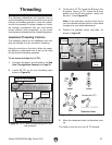
The following subsections will describe how to
use the threading controls and charts to set up the
lathe for a threading operation. If you are unfamil-
iar with the process of cutting threads on a lathe,
we strongly recommend that you read books,
review industry trade magazines, or get formal
training before attempting any threading projects.
Headstock Threading Controls
The threading charts on the headstock face dis-
play the settings for inch and metric threading.
Using the controls on the lathe, follow the exam-
ple below to understand how to set up the lathe
for the desired threading operation.
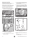
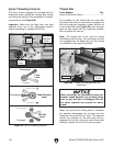
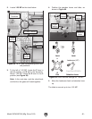
To set levers and dials for 16 TPI:
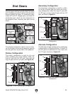
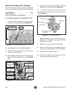
1. Configure the gears, as instructed in the End
Gear Configuration Example on Page 56.
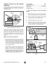
2. Locate 16 TPI on the inch threading chart
shown in Figure 86.
Threading
3. To the left of 16 TPI, locate the E lever in the
2 position. Above 16 TPI, locate the F lever
position and the G dial position—which will
be set to 1 (see Figure 86).
Note: In the next step, use the chuck key to
rock the spindle back-and-forth to help mesh
the gears as you make adjustments.
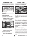
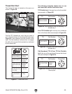
4. Position the gearbox levers and dials, as
shown in Figure 87.
Figure 86. 16 TPI and corresponding lever and
dial positions.
F Lever
Position
G Dial
Position
16 TPI
E
Lever
F
Lever
G
Dial
G
5
6
7
8
9
1
0
1
1
1
2
3
4
3 2 1
mm
˶
Selection Lever
Feed Rod (DOWN)
Leadscrew (UP)
Figure 87. Lever and dial settings for 16TPI.
Lever & Dial Positions
E Lever Position
5. Move the leadscrew feed rod selection lever
up.
The lathe is now set up to cut 16 TPI threads.
Selection
Lever
E Lever
Position
F Lever
Position
G Dial
Position