


06/00 - 31 of 90 - 0116 7201
Rev. 00 © 2000 Hans Pausch Röntgengerätebau Graf-Zeppelin-Str. 1 D-91056 Erlangen ALL RIGHTS RESERVED Ru
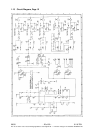
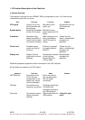
1.15 Function Description of the Controller
a. System Overview
The electronic controller for the UROMAT 3000 is comprised of a max. of 5 units that are
connected to each other via a bus.
UNIT FUNCTION LOCATION REMARK
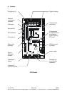
CPU board
Central unit for the
entire controller with
all interfaces.
Behind the cover
panel, top.
All connectors on the
CPU board are
labeled.
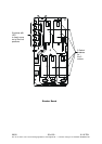
Breaker board
Board with 5 breakers
for the 5 AC motors.
Behind the cover
panel, below the CPU
board.
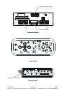
Footswitch
Operation using
pedals, equivalent to
control unit, but does
not have all functions.
Metal housing on the
floor, connected to
the CPU board via
cables.
If there is a foot-
switch, not absolutely
necessary for
operation.
Control unit
Portable manual
control unit with all
functions.
External, connected
by a spiral cable to
the CPU.
If there is a foot-
switch, not absolutely
necessary for
operation.
Display unit
Display of the tilt
angle and of various
statuses.
Permanently mounted
on the housing.
Connected to the
CPU by cable.
Not absolutely
necessary for
operation.
Additional peripheral equipment can be connected via the USS interface.
All interfaces are located on the CPU board:
INTERFACE FUNCTION MODE REMARK
MOTRON bus Connection of the
CPU in the star
configuration to the
display unit, control
unit and footswitch.
Serial, two-wire bit
bus via optocoupler
with full duplex
connection.
USS bus Connection to the
frequency converters.
Serial two-
wire bit bus
via RS485 with
full duplex connection
with USS protocol.
Fiber optic Connection to status
display (customer
request)
Optical serial bus with
USS protocol.
1 direction only:
write!