


0116 7201 -44 of 90 - 06/00
Rev. 00 © 2000 Hans Pausch Röntgengerätebau Graf-Zeppelin-Str. 1 D-91056 Erlangen ALL RIGHTS RESERVED Ru
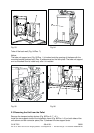
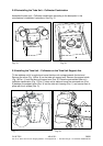
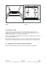
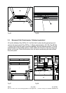
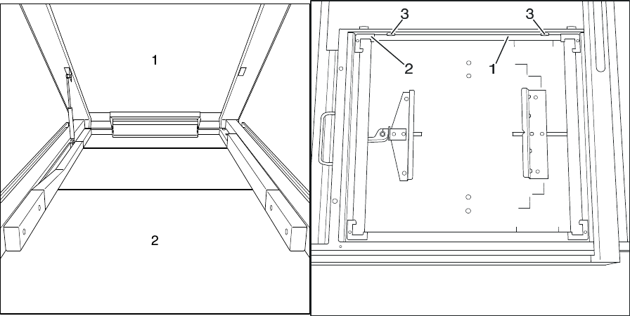
Fig.25 Fig. 26
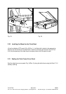
2.13 Laying the I.I. Cable
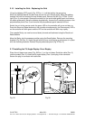
First lay the I.I. cable coming from the wall through the flexible hose (Fig. 23/ Pos. 9),
through the back wall (Pos. 10) and then – if it is coming directly through the floor – to the
cable channel (Fig. 23/Pos. 11) and up into the unit base.
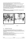
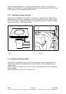
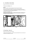
Lay the I.I. cable parallel to the cables for the unit controller to the cable outlet (on the side of
the unit base) (Fig. 25/Pos. 4).
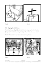
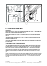
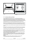
Remove the flexible hose (Fig. 26/Pos. 1). Pull the I.I. cable through the flexible hose to the
table, place it in the flexible plastic link chain (Pos. 2) and lay it to the I.I. connector (Pos. 3).
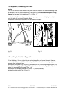
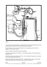
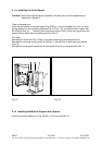
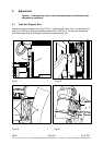
2.14 Making the Power Connection through the Generator
Remove the temporary power connection and connect the power via the generator.