


0116 7201 -86 of 90 - 06/00
Rev. 00 © 2000 Hans Pausch Röntgengerätebau Graf-Zeppelin-Str. 1 D-91056 Erlangen ALL RIGHTS RESERVED Ru
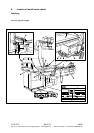
6. Board Replacement
All boards are connected to each other by connectors and are replaceable. After they have
been replaced correctly, they should perform a self test after power is switched on and log
themselves into the CPU.
The CPU board and breaker board are accessible after opening the URO cover panel. They
are seated on several round snap-on mounts, each of which musts be pressed through.
The footswitch board is accessible only after opening the metal housing.
The control unit with spiral must be completely replaced.
The display with connection cable must be completely replaced.
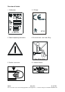
Do not disconnect plug-in connections that are under voltage!
7. Version Update
Only the software of the CPU board can be updated to the latest version. The software in the
other board cannot be updated.
The update is performed by replacing the EPROM on the processor module.
EPROM's are CMOS components. Please observe the guidelines for EMI protection.