


0116 7201 -46 of 90 - 06/00
Rev. 00 © 2000 Hans Pausch Röntgengerätebau Graf-Zeppelin-Str. 1 D-91056 Erlangen ALL RIGHTS RESERVED Ru
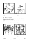
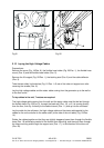
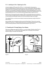
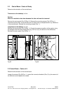
2.16 Installing the Grid – Replacing the Grid
Lift up the tabletop (CFC panel) (Fig. 27/Pos. 1), it will be held by the gas spring.
Move the tabletop towards the back and remove the front Nirosta panel. Move the tabletop
towards the front and remove the rear Nirosta panel. Remove the left (Fig. 27/Pos. 3) and
right (Pos. 4) cover panels. Remove the screws for the spiral cable guide panel and remove
the cable guide panel. Move the tabletop longitudinally, remove the 6 mounting screws in the
polycarbonate panel (Pos. 2) and remove the polycarbonate panel towards the front.
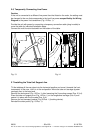
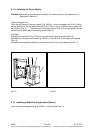
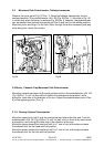
Switch the unit to the service mode, the green LED on the controller will go on and stay on.
Press the Store and Reset buttons on the controller simultaneously, the three memory LED’s
on the controller will blink green and the LED on the controller will blink very rapidly.
The cassette Bucky can now be moved slowly forward and backward using the Recall and
Reset buttons.
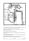
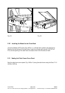
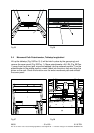
Move the Bucky into the exposure position using the Recall button. Remove the mounting
brackets (Fig. 28/ Pos. 2). Insert the grid with the focus mark facing up and secure it in place
with the mounting brackets. Reinstall the polycarbonate panel (Fig. 27Pos. 2).
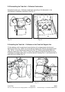
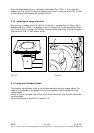
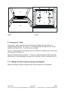
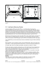
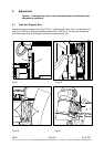
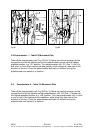
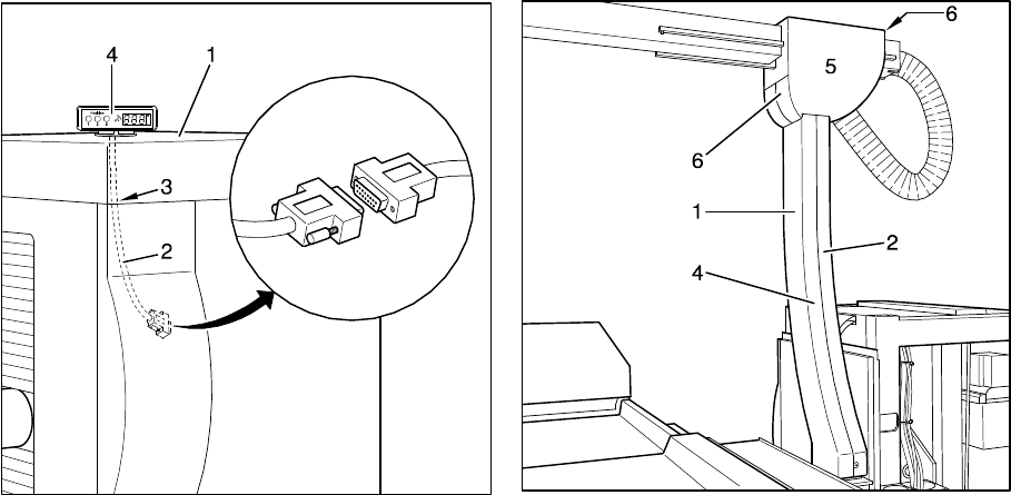
2.17 Installing the Tilt Angle Display- Error Display
Place the unit base cover panel (Fig. 29/Pos. 1) on the unit base. Guide the cable (Pos. 2)
into the conduit (Pos. 3), install the tilt angle display (Pos. 4) and plug in the connector.
Secure the plug-in connector with cable ties.
Fig. 29 Fig. 30