


06/00 - 55 of 90 - 0116 7201
Rev. 00 © 2000 Hans Pausch Röntgengerätebau Graf-Zeppelin-Str. 1 D-91056 Erlangen ALL RIGHTS RESERVED Ru
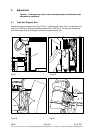
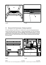
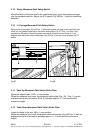
3.12 Bucky Movement Path Safety Switch
Move the Bucky to the foot end to the mechanical stop, move the system carriage
into the exposure position. Adjust the S12 switch (Fig. 66/Pos. 1) so that it positively
switches.
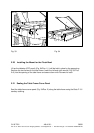
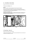
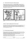
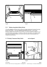
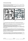
3.13 I.I. Carriage Movement Path Safety Switch
Remove the cover panel (Fig. 65/Pos. 1). Move the system carriage to the head end until
there is 3 mm distance and adjust the switch strike plate (Fig. 67/ Pos. 1) so that it just
actuates the S6 switch. Move the system carriage to the foot end until there is 3 mm
distance and adjust the switch strike plate (Fig. 67/Pos. 2) so that it just actuates the S7
switch.
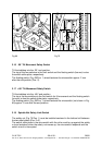
Fig.67 Fig.68
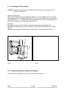
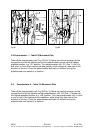
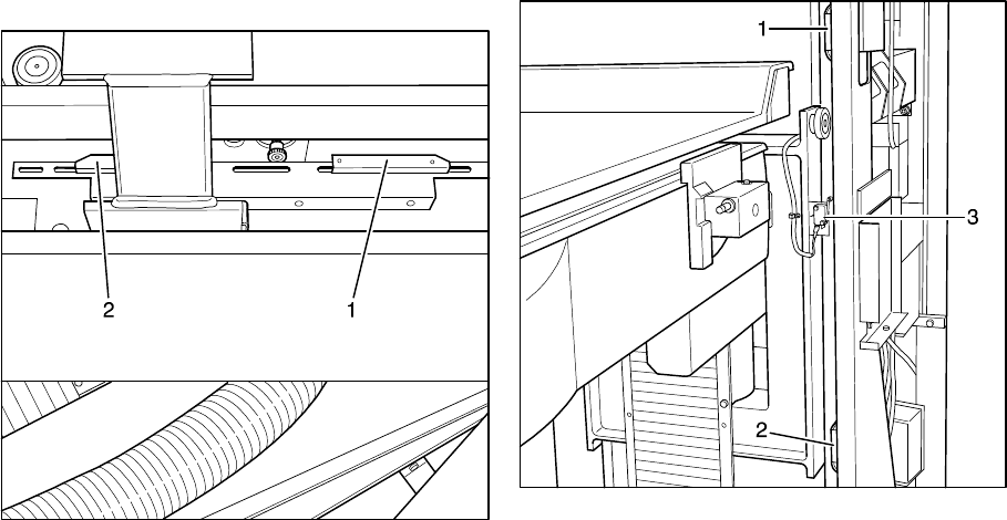
3.14 Table Up Movement Path Switch Strike Plate
Raise the table to max. 1225+/-10 mm position.
When the software limit is set, the top switch strike plate (Fig. 68 / Pos. 1) can be
adjusted so that the limit switch (Pos. 3) actuates approx. 2 - 5 mm behind the
maximum height.
3.15 Table Down Movement Path Switch Strike Plate
Lower the table to the min. 680+/-10 mm position.
When the software limit is set, the bottom switch strike plate (Fig. 68/ Pos. 2) can be
adjusted so that the limit switch actuates approx. 2 - 5 mm behind the minimum
height.