06/00 - 51 of 90 - 0116 7201
Rev. 00 © 2000 Hans Pausch Röntgengerätebau Graf-Zeppelin-Str. 1 D-91056 Erlangen ALL RIGHTS RESERVED Ru
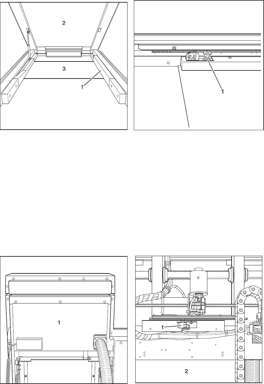
Fig.55 Fig.56
3.4 Movement Path Potentiometer, Tabletop longitudinal
Lift up the tabletop (Fig. 55/Pos. 2) (it will be held in place by the gas spring) and
remove the cover panel (Fig. 55/Pos. 1). Move potentiometer =AU -R4 (Fig. 56/Pos.
1) away from the pinion rack, move the tabletop into the centered position. Turn the
potentiometer to the middle position, mesh it back into the pinion rack and align the
pinion on the rack. Check the function over the entire movement path and reinstall
the cover panel.
Fig.57 Fig.58


