0116 7201 -56 of 90 - 06/00
Rev. 00 © 2000 Hans Pausch Röntgengerätebau Graf-Zeppelin-Str. 1 D-91056 Erlangen ALL RIGHTS RESERVED Ru
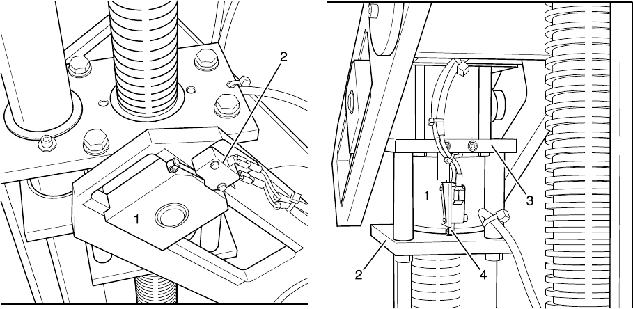
Fig.69 Fig.70
3.16 -20° Tilt Movement Safety Switch
Tilt the tabletop into the -20° end position.
The top of the two switches is the limit switch and the floating switch (bronze) is also
the switch strike plate, respectively.
The floating switch (Fig. 69/Pos. 1) should actuate the microswitch approx. 2 mm
after the end position (Pos. 2).
3.17 +88° Tilt Movement Safety Switch
Tilt the tabletop into the +88° end position.
The top o the two switches is the limit switch for tilt movement and the floating switch
(bronze) is also the switch strike plate, respectively.
The floating switch (Fig. 69/Pos. 1) should actuate the microswitch (not shown in Fig.
69) approx. 2 mm after the end position.
3.18 Spindle Nut Safety Limit Switch
The safety nut (Fig. 70/Pos. 1) must be installed centered in the bottom half between
the two steel plates (Pos. 2+3).
The switch strike plate in the microswitch with the roller must be up against the safety
nut and actuated; when the safety nut moves up, the microswitch responds and the
switch circuit is interrupted.


