


06/00 - 43 of 90 - 0116 7201
Rev. 00 © 2000 Hans Pausch Röntgengerätebau Graf-Zeppelin-Str. 1 D-91056 Erlangen ALL RIGHTS RESERVED Ru
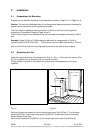
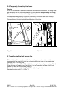
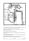
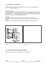
Fig. 23
Lay the cables through the support arm towards the back, through the flexible hose (Pos. 22)
and through the carriage (Pos. 23) to the tube and to the collimator.
Guide the cable for the control handle (Pos. 24) to the connector strip (Pos. 25) in the
support arm and clamp it in place.
Secure the cables in place with the cable ties provided.
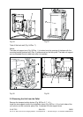
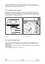
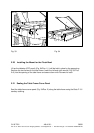
Reinstall the cable deflector (Fig. 22/Pos. 1) the latching studs (Pos. 2) and reinstall the lift
magnet (Pos. 3).
Reinstall the two safety switches (Fig. 21/Pos. 1+2) for the tube unit support arm and secure
them in place with the screws (Pos. 8).
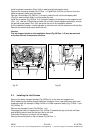
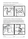
Reinstall the flexible hose holder (Fig. 23/Pos. 1), the flexible hose mount (Pos. 3) and the
flexible hose holder (Pos. 5). Reinstall the cover panel (Fig. 18/Pos. 6).