


0116 7201 -52 of 90 - 06/00
Rev. 00 © 2000 Hans Pausch Röntgengerätebau Graf-Zeppelin-Str. 1 D-91056 Erlangen ALL RIGHTS RESERVED Ru
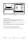
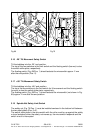
3.5 Movement Path Potentiometer, Tabletop transverse
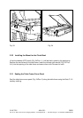
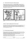
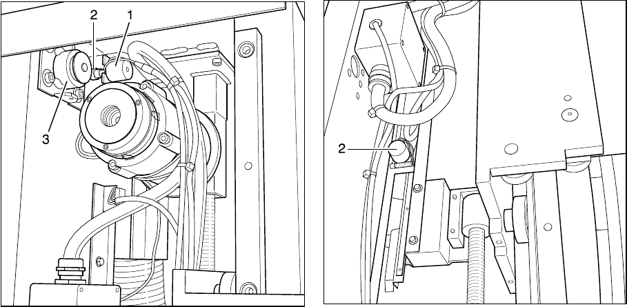
Remove the cover panel (Fig. 57/Pos. 1). Move the tabletop transversely into the
centered position, lift up potentiometer =AU -R6 (Fig. 58/Pos. 1) (the view in Fig. 58
is visible only when the cover is removed Fig. 55/Pos. 3, however, the potentiometer
can be reached from behind through the slot Pos.2) and set it to the middle position.
Mesh the pinion and align it to the rack. Move through the entire movement path and
while doing this, check the function.
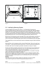
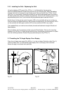
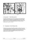
Fig.59 Fig.60
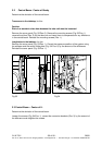
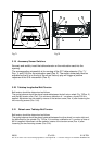
3.6 Bucky - Cassette Tray Movement Path Potentiometer
Move the cassette carriage into the park position and turn the potentiometer =AU -R5
(Fig. 59/Pos. 1) until it is one half turn before the mechanical end position, while
doing this, take note of the direction of the turn. Adjust the potentiometer pinion (Pos.
2) to the opposing pinion (Pos. 3).
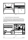
3.7 I.I. Carriage System Potentiometer
Move the support arm until it is at the mechanical end stop at the foot end. Turn the
potentiometer =AU -R2 (Fig. 60/Pos. 2) until it is half a turn in front of the mechanical
end position; while doing this, take note of the direction of the turn.
Move the system toward the head end until it is 7 mm in front of the stop and save
the software limit for the head-end limit position.
Move the system toward the head end until it is 7 mm in front of the stop and save
the software limit for the foot-end limit position.