


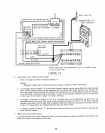

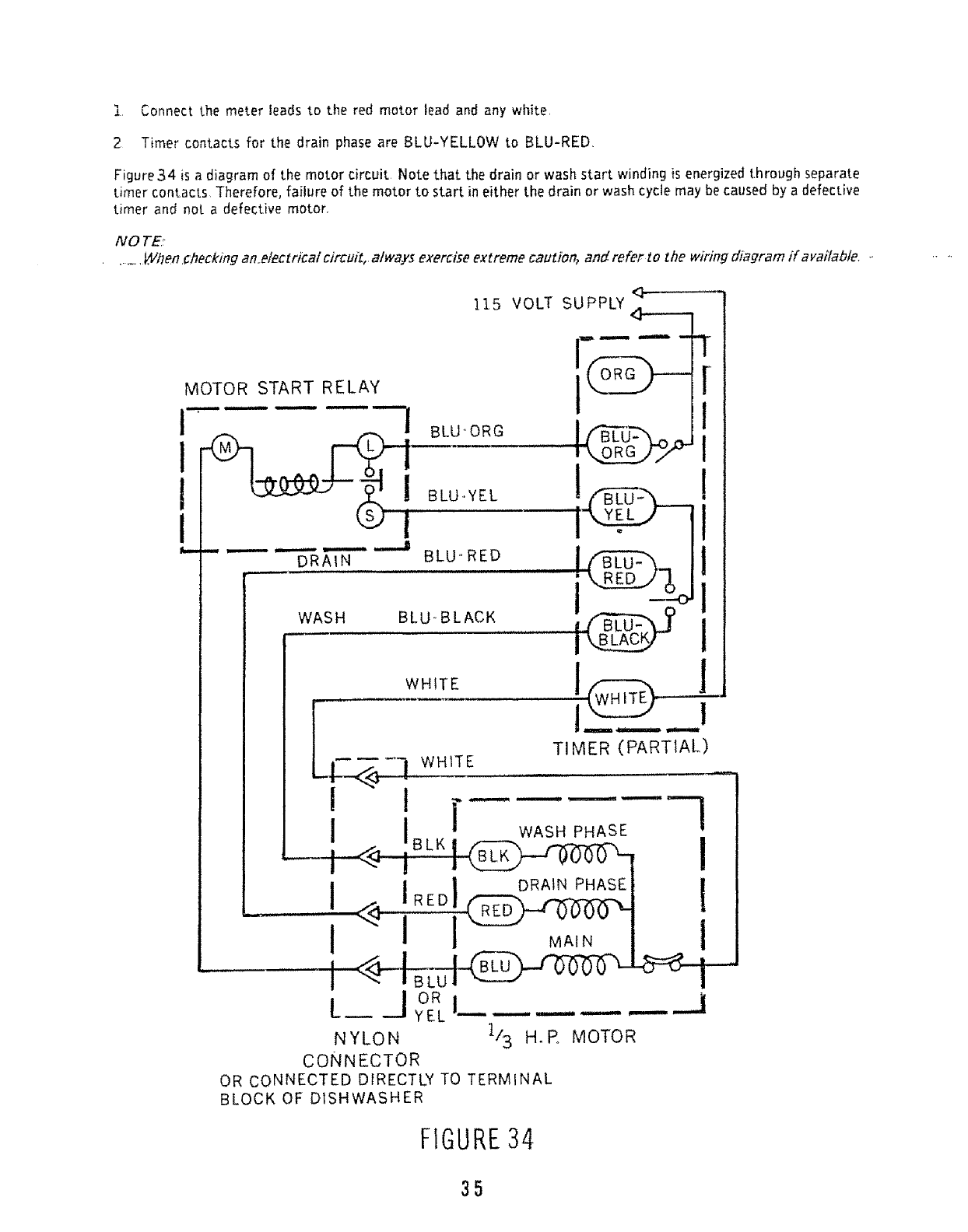
t Connect the meter leads to the red motor lead and any white,
2 Timer contacts for the drain phase are BLU-YELLOW to BLU-RED.
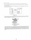
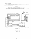
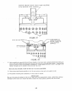
Figure34 is a diagram of the motor circuit Note that the drain or wash start winding is energizedthrough separate
timer contacts Therefore, failure of the motor to start in either the drain or wash cycle may becaused by a defective
timer and not a defective motor.
NO TE
_Vhen.checkingan e/ectricat cJrcuiZ,atways exerciseextreme cautiOr_ and refer to the wiring diagram if availabfe. ..
MOTOR
I
!
I
115 VOLT SUPPLY
START RELAY __
--- ---_-7 B_O'ORG Ir__-u--'___
k
DRAIN
,,,,,,,,,,,,
WASH
!
........BLu ED
T
[
I
WHITE ..............................._.
LI__._<_ WHITE TIMER (PARTIAL)
i i r-- ----7
i IBLK I WASHPHASE
--i__ !
_. !,,_ IR_D!_°_'" P"_ J
I I ! _,. I
I i°R_.... -----J
NYLON 1/3 H.R MOTOR
CONNECTOR
OR CONNECTED DIRECTLY TO TERMINAL
BLOCK OF DISHWASHER
FIGURE34
35