


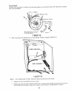
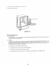
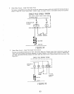

Power Miser Circuits - Single Pole Single Throw
The heater is controlled by cam switch B-3 during the washes and rinses, and by cam switch B-7 during the dry as
shown in Figure 94 [f the "Power Miser" switch is open, the heater circuit is interrupted during the dry period
SINGLEPOLESINGLETHROW
ORANGE BUS
TIMER
POWER MISER
_ HEATER
WHITE
FIGURE94
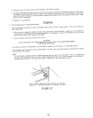
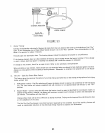
Power Miser Circuits - Single Pole Double Throw Switch
The heat is controlled primarily by the "Red" cam switch When the "'Orange" power miser connection is closed, the
"Red" cam switch energizes the heater whenever it is closed However, if the power miser is closed to "ORG-BLUE,"
the "Red" cam switch can only energize the heater when the motor circuit is closed (washes and rinses only). (See
Figure 95 )
SINGLEPOLEDOUBLEIHROW
pORTION OF
TIMER
\
i1_ MISER
_ HEATER
IF WHITE
I
.%1
R
TO MOTOR
CIRCUIT
FIGURE95
83