


OPERATION
B4.11 B4.11
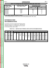
VANTAGE® 500
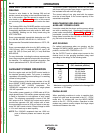
TABLE B3.4 – VANTAGE 500 EXTENSION CORD LENGTH RECOMMENDATIONS
Current
(Amps)
15
15
20
20
25
30
38
50
Voltage
(Volts)
120
240
120
240
240
240
240
240
Load
(Watts)
1800
3600
2400
48010
6000
7200
9000
12000
30
60
(9)
(18)
40
75
30
60
(12)
(23)
(9)
(18)
75
150
50
100
90
75
(23)
(46)
(15)
(30)
(27)
(23)
125
225
88
175
150
120
100
(38)
(69)
(27)
(53)
(46)
(37)
(30)
175
350
138
275
225
175
150
125
(53)
(107)
(42)
(84)
(69)
(53)
(46)
(38)
300
600
225
450
250
300
250
200
(91)
(183)
(69)
(137)
(76)
(91)
(76)
(61)
Maximum Allowable Cord Length in ft. (m) for Conductor Size
Conductor size is based on maximum 2.0% voltage drop.
14 AWG 12 AWG 10 AWG 8 AWG 6 AWG 4 AWG
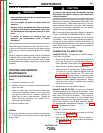
EXTENSION CORD
RECOMMENDATIONS
An extension cord can be used with the auxiliary power
outputs as long as it is of ample size. Table B.5 lists
permissible extension cord lengths based on conduc-
tor size and auxiliary power output.
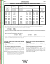
TABLE B3.3 Vantage 500 Duetz Simultaneous Welding and Power Loads
Welding Output Permissible Power Watts Permissible Auxiliary
at NEMA Voltage (Unity Power Factor) Current in Amperes
(V=.04I + 20) @ 120VAC * +/- 10% @ 240 VAC +/- 10%
0-250A/30V 12,000 100** 50
350A/34V 8,100 68** 34
400A/36V 5,600 46 23
450A/38V 2,900 24 12
500A/40V 000
* Each duplex receptacle is limited to 20 amps.
** Not to exceed 50A per 120 VAC branch circuit when splitting the 240 VAC output.
Return to Section TOC Return to Section TOC Return to Section TOC Return to Section TOC
Return to Master TOC Return to Master TOC Return to Master TOC Return to Master TOC