


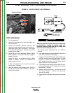
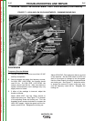
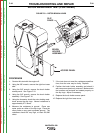
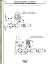

SLIP
RINGS
BRUSH
HOLDER
ASSEMBLY
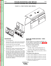
ACCESS PANEL
FIGURE F.8 – ROTOR BRUSH LEADS
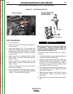
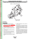
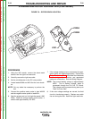
ROTOR RESISTANCE TEST (CONTINUED)
PROCEDURE
1. Conduct this test with the engine off.
2. Using the 3/8" wrench, remove the right front case
side.
3. Using the 3/8" wrench, remove the brush holder
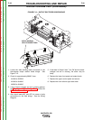
access panel. See Figure F.10.
4. Using the 3/8" wrench, remove the brush holder
assembly. See Figure F.10.
5. Using the ohmmeter, check the rotor winding resis-
tance across the slip rings. Normal resistance is
approximately 27.0 ohms.
6. Measure the resistance to ground. Place one
meter probe on either of the slip rings. Place the
other probe on any good unpainted ground. The
resistance should be very high, at least 500,000
ohms.
7. If the test does not meet the resistance specifica-
tions, then the rotor may be faulty. Replace.
8. Position the brush holder assembly and attach it
with two screws previously removed. Make certain
the brushes are centered and seated properly on
the slip rings. Adjust if necessary.
9. Replace the brush holder access panel.
10. Replace the right front case cover.
TROUBLESHOOTING AND REPAIR
F-30 F-30
VANTAGE® 500
Return to Section TOC Return to Section TOC Return to Section TOC Return to Section TOC
Return to Master TOC Return to Master TOC Return to Master TOC Return to Master TOC