


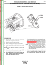
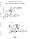
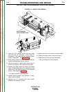
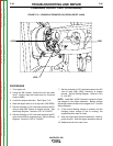

WELD WINDING
LEAD CONNECTIONS
W1
W6
W3
W2
W5
W4
FIGURE F.14 – DIODE LEAD REMOVAL
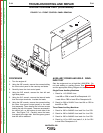
OUTPUT RECTIFIER BRIDGE TEST(CONTINUED)
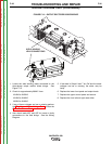
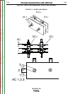
9. Using the 7/16” wrench, remove the stator leads
from the three AC terminals. Label leads for
reassembly. Note leads and AC terminals place-
ment for reassembly. See Figure F.15.
10. Electronically isolate the 3 AC terminals leads by
carefully bending them out into “free air”
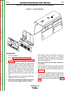
11. With an ohmmeter or diode tester, check each of
the 3 AC terminals to their respective heat sinks.
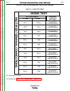
12. Reverse the tester leads and check the diodes
again. Diodes should have a low resistance in one
polarity and very high resistance in the opposite
polarity. See diode test Table F.2.
* One open diode will not be detected.
13. Replace rectifier bridge if any “shorted” or “open”
diode as tests indicate.
14. Replace the AC terminals and stator leads.
Assemble the washers and nuts.
15. Replace the lower front panel and output leads.
16. Replace the upper control panel and secure.
17. Replace the front left and right case sides.
* One open diode will not be detected.
TROUBLESHOOTING AND REPAIR
F-39 F-39
VANTAGE® 500
Return to Section TOC Return to Section TOC Return to Section TOC Return to Section TOC
Return to Master TOC Return to Master TOC Return to Master TOC Return to Master TOC