


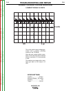
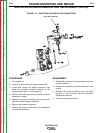
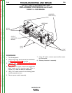
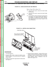

OUTPUT
RECTIFIER
BRIDGE
2 7/16"
BOLTS
2 7/16"
BOLTS
2 1/2"
NUTS
CHOPPER
MODULES (2)
HEATSINKS
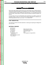
FIGURE F.19 – DOOR REMOVAL
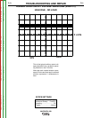
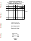
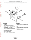
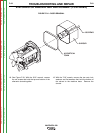
OUTPUT RECTIFIER REMOVAL AND
REPLACEMENT PROCEDURE (continued)
PROCEDURE
1. Turn the engine off.
2. Perform the output panel removal as described in
the Case Cover Removal procedure.
3. Perform the Chopper Module Capacitor
Discharge procedure.
4. Using the 7/16" wrench, remove the appropriate
stator leads and AC terminals leads. Refer to
Figure F.19. Label the leads for reassembly.
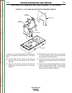
5. Using 7/16” socket remove 4 bolts holding power
module assembly to base.
6. Remove power module assembly.
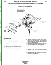
7. Using 1/2” socket, remove output rectifier assem-
bly and replace.
8. Reverse procedure for assembly.
TROUBLESHOOTING AND REPAIR
F-58 F-58
VANTAGE® 500
Return to Section TOC Return to Section TOC Return to Section TOC Return to Section TOC
Return to Master TOC Return to Master TOC Return to Master TOC Return to Master TOC