


B1
B4
B5
B6
B2
B3
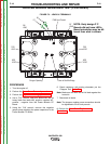
87
W8
LEAD
W7
LEAD
POS
LEAD
POS
LEAD
NEG
LEAD
NEG
LEAD
88
PWM Input Present
Power at Recitifier BridgeChopper Operating
LED3
LED2
LED1
LXXXX
X-
X
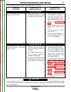
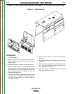
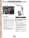
FIGURE F.3 – LEADS & TERMINALS
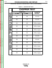
CHOPPER MODULE RESISTANCE TEST (CONTINUED)
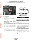
PROCEDURE
1. Turn the engine off.
2. Perform the Case Cover Removal procedure.
3. Perform the Capacitor Discharge procedure.
4. Use a 7/16” wrench, label and disconnect the six
heavy black flex leads W8, positive, negative W7,
positive , negative from the Power Module PC
Board.
5. Using the 7/16’ wrench, remove the negative
jumper strap attaching the power capacitors to the
Power Module PC Board.
6. Check resistance with analog ohmmeter per the
“Chopper Test” Table F.1.
Note: Make sure the bolts do not fall back against the
heat sink.
7. Reconnect all leads.
Note: The chopper module screw connections should
be tightened to 50-60 inch-pounds.
8. Perform the Case Cover Replacement
Procedure.
TROUBLESHOOTING AND REPAIR
F-18 F-18
VANTAGE® 500
NOTE: Early design P C
Boards did not have LED’s.
Board orientation may be dif-
ferent than what is shown.
Return to Section TOC Return to Section TOC Return to Section TOC Return to Section TOC
Return to Master TOC Return to Master TOC Return to Master TOC Return to Master TOC