


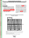
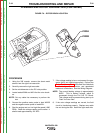
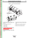
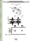
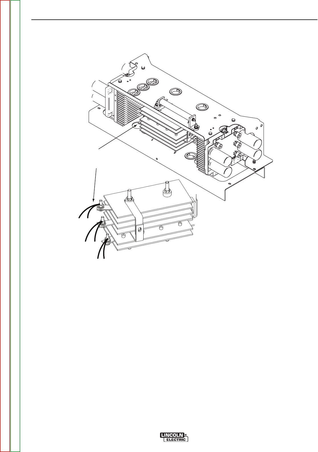
WELD WINDING
LEAD CONNECTIONS
W1
W6
W3
W2
W5
W4
FIGURE F.12 – OUTPUT RECTIFIER DIODE BRIDGE
STATOR VOLTAGE TEST (CONTINUED)
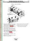
1. Locate the weld winding leads connected to the
three-phase output rectifier diode bridge. See
Figure F.12.
2. Check for approximately 68VAC from:
W1/W6 to W2/W3.
W1/W6 to W4/W5
W2/W3 to W4/W5
3. If any of these voltages are low or missing perform
the Flashing and Rotor Voltage Test and also the
Rotor Resistance Test.
4. Also check leads #6F and #5P for loose or faulty
connections to the field bridge. See the Wiring
Diagram.
5. If the tests in Steps 6 and 7 are OK and the stator
voltages are low or missing, the stator may be
faulty.
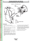
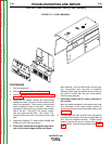
6. Replace the lower front panel and output leads.
7. Replace the upper control panel and secure.
8. Replace the front left and right case sides.
TROUBLESHOOTING AND REPAIR
F-36 F-36
VANTAGE® 500
Return to Section TOC Return to Section TOC Return to Section TOC Return to Section TOC
Return to Master TOC Return to Master TOC Return to Master TOC Return to Master TOC