


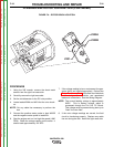
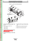
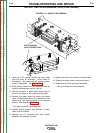
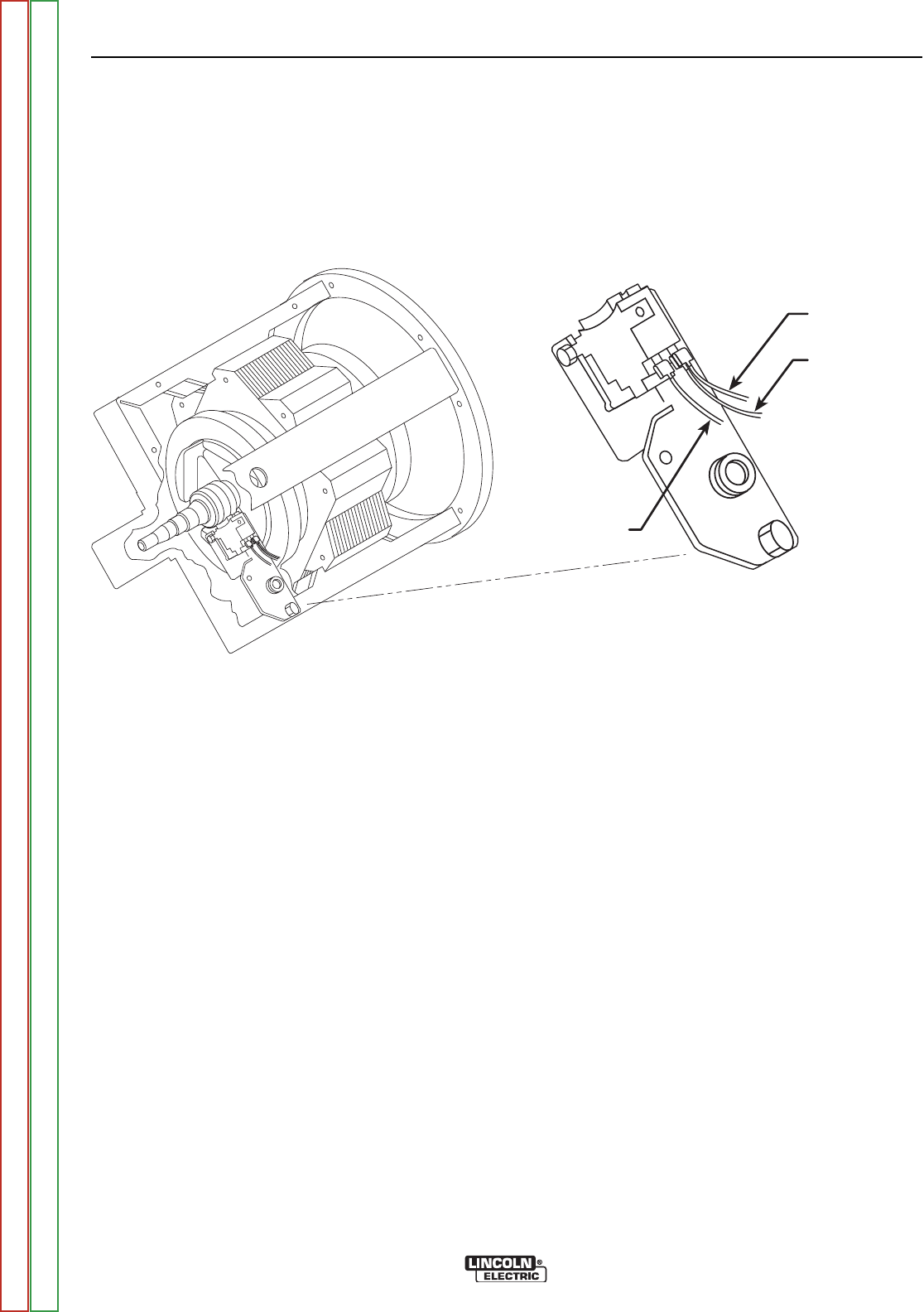
#200A
#200B
#201
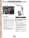
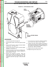
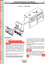
FIGURE F.9 – ROTOR BRUSH LOCATION
FLASHING AND ROTOR VOLTAGE TEST(CONTINUED)
PROCEDURE
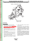
1. Using the 3/8" wrench, remove the sheet metal
screws from the right front case side.
2. Carefully remove the right case side.
3. Set the volt/ohmmeter to the DC volts position.
4. Locate leads #200A and #201A at the rotor brush-
es.
NOTE: Cut any cable ties necessary to perform the
test.
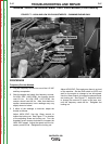
5. Connect the positive meter probe to lead #200B
and the negative meter probe to lead #201.
6. Start the engine and run it at high idle speed (1900
RPM). Check the voltage reading on the meter. It
should read approximately 120 VDC.
7. If the voltage reading is low or not present, the gen-
erator field is not functioning properly. Perform the
Rotor Resistance Test. Also check the field diode
rectifier bridge, filter capacitor, and associated
leads and connections. See the Wiring Diagram.
NOTE: The normal flashing voltage is approximately
9VDC. This is battery voltage, which is
processed through the Pull Coil PC Board.
This voltage must be present during start-up to
"flash" the rotor field.
8. If the rotor voltage readings are normal, the field
circuit is functioning properly. Replace any cable
ties cut during the test. Install the right case side.
TROUBLESHOOTING AND REPAIR
F-32 F-32
VANTAGE® 500
Return to Section TOC Return to Section TOC Return to Section TOC Return to Section TOC
Return to Master TOC Return to Master TOC Return to Master TOC Return to Master TOC