


OPERATION
B5.11 B5.11
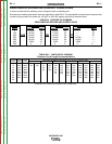
VANTAGE® 500
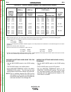
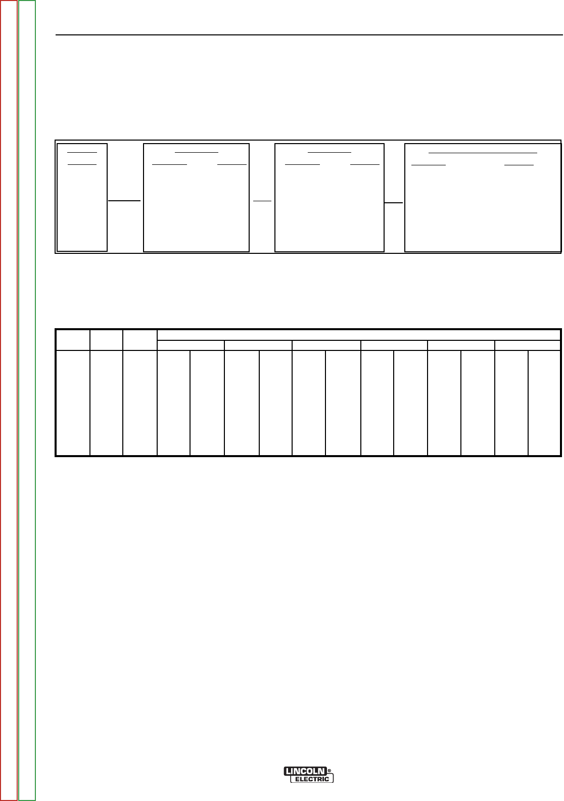
SIMULTANEOUS WELDING AND AUXILIARY POWER LOADS
It must be noted that the auxiliary power ratings are with no welding load.
Simultaneous welding and power loads are specified in table B5.4. The permissible currents shown assume that
current is being drawn from either the 120 VAC or 240 VAC supply (not both at the same time).
TABLE B.4 VANTAGE 500 CUMMINS
SIMULTANEOUS WELDING AND POWER LOADS
WELD
AMPS
0
100
200
250
300
400
500
1 PHASE
WATTS AMPS
12,000 50
12,000 50
12,000 50
12,000 50
10,000 42
5,600 23
0 0
3 PHASE
WATTS AMPS
20,000 50
17,800 43
14,000 34
12,000 29
10,000 24
5,600 13
0 0
BOTH 1 AND 3 PHASE
WATTS AMPS
------ 50
------ 50
------ 50
12,000 ------
10,000 ------
5,600 ------
0 0
PLUS
OR
OR
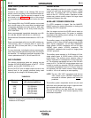
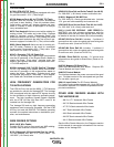
TABLE B5.5 VANTAGE 500 CUMMINS
Extension Cord Length Recommendations
Current
(Amps)
15
15
20
20
25
30
38
50
Voltage
(Volts)
120
240
120
240
240
240
240
240
Load
(Watts)
1800
3600
2400
4800
6000
7200
9000
12000
30
60
(9)
(18)
40
75
30
60
(12)
(23)
(9)
(18)
75
150
50
100
90
75
(23)
(46)
(15)
(30)
(27)
(23)
125
225
88
175
150
120
100
(38)
(69)
(27)
(53)
(46)
(37)
(30)
175
350
138
275
225
175
150
125
(53)
(107)
(42)
(84)
(69)
(53)
(46)
(38)
300
600
225
450
250
300
250
200
(91)
(183)
(69)
(137)
(76)
(91)
(76)
(61)
Maximum Allowable Cord Length in ft. (m) for Conductor Size
Conductor size is based on maximum 2.0% voltage drop.
14 AWG 12 AWG 10 AWG 8 AWG 6 AWG 4 AWG
Return to Section TOC Return to Section TOC Return to Section TOC Return to Section TOC
Return to Master TOC Return to Master TOC Return to Master TOC Return to Master TOC