


INSTALLATION
A5.8 A5.8
VANTAGE® 500
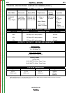
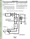
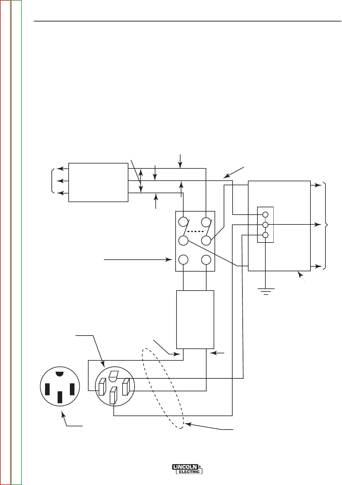
Figure A5.1 Connection of the Vantage to Premises Wiring
1. Install the double-pole, double-throw switch
between the power company meter and the
premises disconnect.
Switch rating must be the same or greater than the cus-
tomer’s premises disconnect and service over current
protection.
2. Take necessary steps to assure load is limited to
the capacity of the Vantage by installing a 50 amp,
240 VAC double-pole circuit breaker. Maximum
rated load for each leg of the 240 VAC auxiliary is
50 amperes. Loading above the rated output will
reduce output voltage below the allow-
able -10% of rated voltage, which may damage
appliances or other motor-driven equipment and
may result in overheating of the Vantage 500
engine.
3. Install a 50 amp 120/240 VAC plug (NEMA Type
14-50) to the double-pole circuit breaker using
four-conductor cable of the proper size and desired
length. (The 50 amp, 120/240 VAC plug is avail-
able in the optional K802R plug kit.)
4. Plug this cable into the 50 amp 120/240 volt recep-
tacle on the Vantage 500 case front.
240 Volt
60 Hz.
3-Wire
Service
POWER
COMPANY
METER
240 VOLT
120 VOLT
120 VOLT
LOAD
N
NEUTRAL
BUS
GROUND
PREMISES
DISCONNECT AND
SERVICE
OVERCURRENT
PROTECTION
GND
N
4 CONDUCTOR COPPER CABLE
SEE NATIONAL ELECTRICAL CODE FOR
WIRE SIZE RECOMMENDATIONS.
240 VOLT
GROUNDED CONDUCTOR
50AMP
240 VOLT
DOUBLE
POLE
CIRCUIT
BREAKER
DOUBLE POLE DOUBLE THROW
SWITCH RATING TO BE THE SAME
AS OR GREATER THAN PREMISES
SERVICE OVERCURRENT
PROTECTION.
50 AMP, 120/240
VOLT PLUG
NEMA TYPE 14-50
50 AMP, 120/240 VOLT
RECEPTACLE
Return to Section TOC Return to Section TOC Return to Section TOC Return to Section TOC
Return to Master TOC Return to Master TOC Return to Master TOC Return to Master TOC