


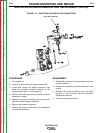
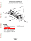
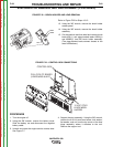
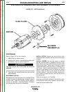
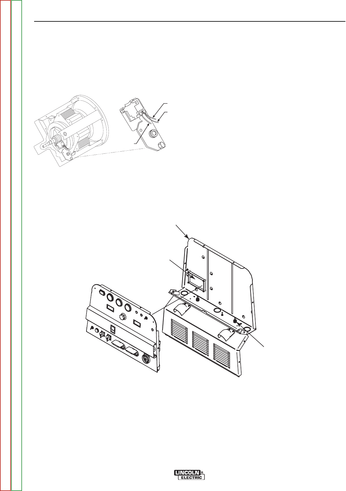
CONTROL BOX
PULL COIL PC BOARD
(LEADS #265 & #227
12 VDC STUD
LEADS #232L
& #232M
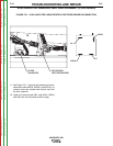
FIGURE F.22 – BRUSH HOLDER AND LEAD REMOVAL
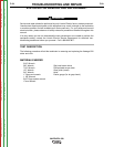
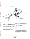
STATOR/ROTOR REMOVAL AND REPLACEMENT (CONTINUED)
PROCEDURE
1. Turn the engine off.
2. Using the 3/8" wrench, remove the battery cover.
Slide the battery out and disconnect the negative
battery cable.
3. Unlatch and open the engine service access door.
See Figure F.1.
4. Support the door assembly. Using the 3/8" wrench,
remove the #10-24 round head screw, lock washer,
flat washer, and nut from the top corner of the door
hinge assembly, where it attaches to the roof.
Remove the support rod.
TROUBLESHOOTING AND REPAIR
F-62 F-62
VANTAGE® 500
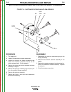
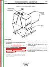
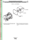
FIGURE F.23 – CONTROL BOX CONNECTIONS
#200A
#200B
#201
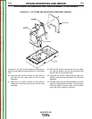
Refer to Figure F.22 for Steps 13-15.
13. Using the 3/8" wrench, remove the brush holder
access panel.
14. Using the 3/8" wrench, remove the brush holder
assembly.
15. Cut the cable tie and then label and remove brush
leads #201(-) and piggy-backed leads #200A(+)
and #200B(+) from the brush holder assembly.
(The piggy-backed leads connect closest to the
stator laminations.)
Return to Section TOC Return to Section TOC Return to Section TOC Return to Section TOC
Return to Master TOC Return to Master TOC Return to Master TOC Return to Master TOC