


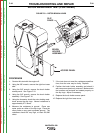
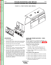
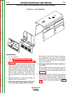
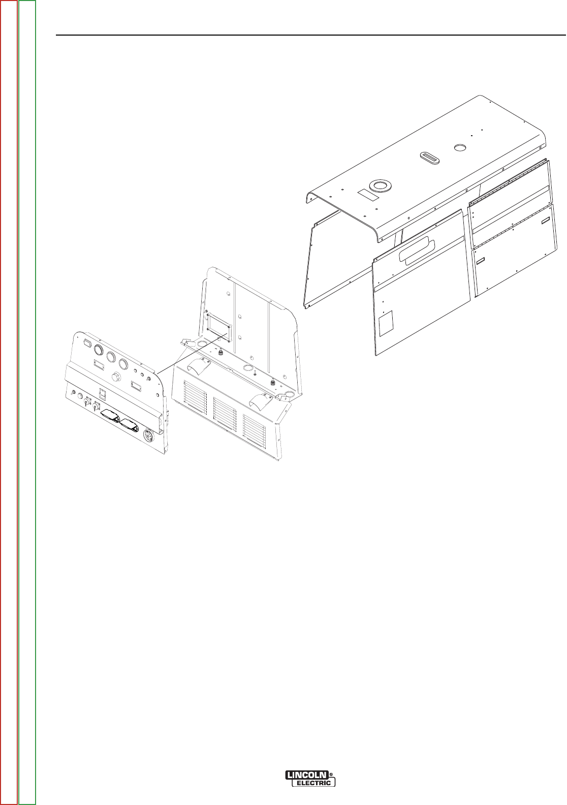
FIGURE F.13 – DOOR REMOVAL
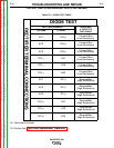
OUTPUT RECTIFIER BRIDGE TEST(CONTINUED)
PROCEDURE
1. Turn the engine off.
2. Perform Case Cover Removal Procedure.
3. Perform Chopper Module Capacitor Discharge
Procedure.
4. Using the 3/8" wrench, remove the three screws
holding the lower front panel (output panel) to the
case front assembly. Then remove the front two
screws holding the top of the panel. These are
accessed in the control box, on the bottom at each
side of the box. Using the 7/16" wrench, discon-
nect the green ground lead. See Figure F.13.
Carefully move the lower front panel to the right
side.
5. Disconnect Bypass PC board leads #206B and
#208 from their in-line connectors.
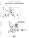
6. Electrically isolate the three-phase input termi-
nals of the output bridge rectifier as follows:
Mark leads W1, W2, and W3 so they can be prop-
erly reconnected after the test is complete.
Remove these leads and position them so they do
not come in contact with any part of the rectifier.
See the wiring diagram.
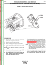
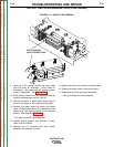
7. Electrically isolate the DC output terminals of
the rectifier:
Mark the leads connected to the positive and neg-
ative terminals of the output bridge rectifier to
assure that they can be reconnected properly. See
Figure F.14.
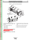
8. Remove leads W4, W5, and W10 from the positive
terminal of the rectifier, and remove leads W6 and
W11 from the negative terminal. Position these
leads so they do not come in contact with any part
of the rectifier. See the wiring diagram and Figure
F.14.
TROUBLESHOOTING AND REPAIR
F-38 F-38
VANTAGE® 500
Return to Section TOC Return to Section TOC Return to Section TOC Return to Section TOC
Return to Master TOC Return to Master TOC Return to Master TOC Return to Master TOC